High Voltage High-Value Resistors, Dividers
High Voltage, High Resistance, High Frequency


High-Value Voltage Resistor Terminology & Glossary
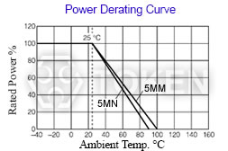
Derating Curve
The curve that describes the relationship between the resistors’s operating temperature and the maximum value of continuous power permitted at that temperature. If the circuit designs permits, the choice of a high ohmic value resistor or divider network will minimize this consideration and improve the resistor's performance because it will operate at lower power.
Critical Resistance Value
The maximum nominal resistance value at which the rated power can be applied continuously without exceeding the maximum working voltage is the critical resistance value. The rated voltage is equal to the maximum working voltage in the critical resistance value. If the circuit designs permits, the choice of a high ohmic value resistor or divider network will eliminate this consideration.
Cermet
A cermet resistive element is made from a mixture of glass and metal oxides. The metal oxide is typically RuO2 or an AgPt alloy. Applying cermet materials to a flat or cylindrical substrate, and then firing them at 850°C produce thick Film resistors. In the electronic industry cermet material is typically called Thick Film paste or ink.
Noise
Resistive noise can have a devastating effect on low-level signals, charge amplifiers, high gain amplifiers, and other applications sensitive to noise. The best approach is to use resistor types with low or minimal noise in applications that are sensitive to noise. Because of their construction and manufacturing processes.
Power Rating
Power ratings are based on physical size, allowable change in resistance over life, thermal conductivity of materials, insulating and resistive materials, and ambient operating conditions. For best results, employ the largest physical size resistors at the less than their maximum rated temperature and power. Never use them continuously at their maximum rating unless you are prepared to accept the maximum allowed life cycle changes. If the circuit designs permits, the choice of a high ohmic value resistor or divider network will minimize the power level and improve the resistor’s performance as it is operating at a lower power level.
Typical Derating Curve
Rated Voltage
The maximum voltage applied continuously to a resistor at the rated ambient temperature. Rated voltage is calculated from the following formula, but it must not exceed the maximum working voltage. Equation: Rated Voltage (V) = (Rated Power (W) × Nominal Resistance Value (Ω))1/2.
High voltage resistors often are potted or operated in oil as the arc over voltage, in air, is approximately 10,000 volts per inch. Token's resistors feature higher voltage ratings due to their high square count and associated design characteristics.
Rated Power
Rated power is the maximum value of power (watts), which can be continuously applied to a resistor at a rated ambient temperature. The basic mathematical relationship is Equation: Power (watts) = (Current (Amps))2 × Resistance (Ohms).
If the circuit designs permits, the choice of a high ohmic value resistor or divider network will minimize the power level and improve the resistor’s performance because it is operating at a lower power and temperature level.
Maximum Working Voltage
The maximum voltage applied continuously to a resistor or a resistor element. The maximum value of the applicable voltage is the rated voltage at the critical resistance value or lower. If the circuit designs permits, the choice of a high ohmic value resistor or divider network will improve the resistor's performance because it will operate at lower power.
Resistor Tolerance
Resistor Tolerance is expressed as the deviation from nominal value in percent and is measured at 25°C only with no appreciable load applied. A resistors value will also change with applied voltage (VCR) and temperature (TCR). For networks, absolute resistor tolerance refers to the overall tolerance of the network. Ratio tolerance refers to the relationship of each resistor to the others. It is often practical to specify tight ratio tolerances and loose absolute tolerances.
Temperature Coefficient of Resistance (TCR)
The Temperature Coefficient of Resistance (TCR) is expressed as the change in resistance in ppm (0.0001%) with each degree of change in temperature Celsius (°C). For example, a resistor with a TCR of +100 ppm/°C will change +0.1% total over a 10-degree change and +1% total over a 100-degree change.
The TCR value quoted on specification sheets is typically quoted as being referenced at +25°C and is the +25°C to +75°C slope of the TCR curve. TCR is typically not linear, but parabolic with temperature, as illustrated by the accompanying fig-1. Often the circuit designer treats the TCR as being linear unless very accurate measurements are needed. MIL STD 202 Method 304 is often referenced as a standard for measuring TCR. The following formula expresses the rate of change in resistance value per 1 °C in a prescribed temperature range:
- TCR (ppm/°C) = (R - Ro) / Ro × 1 / (T - To) × 106
- R: Measured resistance (Ω) at T °C;
Ro: Measured resistance (Ω) at To °C - T: Measured test temperature (°C);
To: Measured test temperature (°C)
In the context of a resistor network, this TCR value is called the absolute TCR in that it defines the TRC of a specific resistor element.
Voltage Coefficient of Resistance (VCR)
The Voltage Coefficient is the change in resistance with applied voltage. This is entirely different and in addition to the effects of self-heating when power is applied. A resistor with a VCR of 100 ppm/V will change 0.1% over a 10 Volt change and 1% over a 100 Volt change. The rate of change in resistance value per 1 Volt in the prescribed voltage range is expressed by the following formula:
- VCR (ppm/V) = (Ro - R) / Ro × 1 / ( Vo - V) × 106
- R: Measured resistance (Ω) at base voltage; V: Base voltage
- Ro: Measured resistance (Ω) at upper voltage; Vo: Upper voltage

Typical Thick Film TCR (Temperature Coefficient of Resistance) Curve
Catalogue Download
Download Terminology & Glossary in PDF file.
General Information of High Voltage, High Ohmic Resistors
Selection of High Voltage Resistors
How to cost effective complete select high voltage resistors?
Token high voltage series can be specified for use in industrial and general purpose high voltage systems, as well as a complete selection of high resistance, Hi-Meg, high-voltage, high frequency, and bulk ceramic resistors for higher average power dissipation.
These High Resistance, High Frequency, High Resistance resistors combine the proven performance of Token resistance system with new cost efficient design elements and high voltage applications.
Detailed specifications, both mechanical and electrical, please contact our sales representative for more information.
High Voltage Applications
Resistors produced from Serpentine Pattern Screen Printing Design or bulk ceramic materials have displayed several key advantages in demanding high-voltage situations, including both continuous-wave and pulse applications.
These include radar and broadcast transmitters, x-ray systems, defibrillators, lasers, and high-voltage semiconductor process equipment applications, where resistors must handle peak voltage anywhere from 8KV to 75KV.
Typical applications include current limit in capacitor charge/discharge, crowbar, and tube-arc circuits. In these uses, bulk ceramic resistors provide low inductance, high average power per unit size, stability at high voltage, and durability at extreme peak-power levels. Film resistors typically cannot withstand high-voltage pulse applications.
RF/Digital Loads and High-Frequency Applications
Token Non-Inductive Voltage Resistors are used extensively for high-frequency RF loads in broadcast and communication equipment because of their non-inductive characteristics.
They provide excellent non-inductive power-handling capacity at frequencies upto the gigahertz range, with no sacrifice in power dissipation.
Film resistors may provide the needed non-inductive characteristics required by such RF applications, but they have size limitations and present reliability problems due to potential film burnout. This is especially true in advanced digital applications such as digital radio and TV transmitters involving pulses at high frequencies.
Application Notes
Due to the high voltage which can appear between the end cap and any adjacent metal part, resistors should be mounted at an adequate distance from other conductors.
An appropriate number of resistors may be screwed together as a stick to provide an assembly which will be capable to withstanding any desired voltage, providing no individual resistor is subject to a greater stress or power dissipation than is recommended in its data sheet, and that appropriate anticorona devices are fitted.
The axial termination should not be bent closer than twice the diameter of the terminal wire from the body of the resistor. When resistors are required to be potted, the preferred encapsulant is a silicone compound.
Oil Immersion
For some high voltage applications it is required to immerse the components in oil or gas to reduce the effects of corona and surface tracking. A special lacquer protected version of the resistor is available, suitable for immersion in transformer oil or SF6.
PDF Catalogue
Download General Info. of High Voltage Resistorsin PDF file.
Download Entire High Voltage Resistor Catalogue in PDF file.