Thick Film Planar Dividers, Through-Hole, High Voltage Resistors (HI83)
Planar Through-Hole Divider (HI83) Introduction
Token Electronic Printing Technology to Achieve a Superior Precision, Thick Film Planar High Voltage Dividers.

Through-hole (HI83) thick film planar divider, high voltage resistor series is a new generation of Token Electronic Technology Co., Ltd. Taking advantage of high-quality ruthenium oxide resistance material to 96% alumina planar ceramic matrix, dividers (HI83) features good thermal conductivity, small size, and high reliability. Custom dividers available with leadwire terminals or with leadless conductive pads.
The planar thick film divider resistor (HI83) provides stable performance over a wide range of resistance values with a voltage rating up to 35KV. The maximum resistance ratio is 1000: 1 (ratio greater than 1000: 1, such as 2000: 1, 4000: 1, and 5000: 1 is available on request) with a minimum resistance ratio of 40: 1.
Low temperature coefficient can be used for high stability circuit applications. Space-saving planar packages provide an alternative to traditional high-voltage resistors. (HI83) is mainly used in precision instruments, drive circuits, power supplies, transformers, high voltage power equipment, and any need to operate in high voltage electrical appliances and other fields.
The main structure of the planar thick film voltage divider (HI83): The terminal connecting conductor and the ruthenium oxide resistive material were printed on the surface of the 96% alumina substrate in a non-inductive pattern. Then apply the screen printing protection, after connect the terminals. Phosphor bronze solder is welded to the lead frame terminal and is immersed in SnAgCu to meet the following IEC weldability requirements.
Thick film (HI83) voltage dividers are RoHS compliant and 100% lead free. For conventional parameters, specifications outside the parameters, or technical requirements, please contact Token.
Download complete specification Thick Film Voltage Dividers (HI83) PDF.
- High precision, Non-Inductance design.
- High voltage, Wide range of resistance.
- Custom design services. RoHS compliant.
- Electric Arc Furnace Damping, High Voltage Buffer Circuit.
- Pulse Modulator, Capacitor Arc Suppression Circuit, Energy Research, High Voltage Buffer Circuit.
- Radar Pulse Forming Network, Impulse Voltage Generator, X-ray/Imaging Equipment, and EMI Lightning Suppression.
(HI83) - Specifications Structure & Dimension (Unit: mm)

(HI83) Planar Radial-Lead Construction |
| Membrane Material (a) | Ruthenium Paste |
| Base Material (b) | 95% Aluminum Oxide, Al2O3 |
| Encapsulating Material (c) | High Temperature Silicone Resin |

(HI83) Dimensions (Unit: mm)
High-Value High-Voltage Divider

(HI83) Divider Schematic
| Part Number | Power Rating (W) | Max. Working Voltage (KV) | L ±0.5 mm | W ±0.5 mm | D ±0.5 mm | P ±1 mm | I ±1 mm | T ±0.5 mm | t ±0.05 mm |
| HI83-04 | 1/4W | 10 | 25 | 5 | 4 | 22.6 | 20 | 2 | 0.6 |
| HI83-02 | 1/2W | 15 | 35 | 5 | 5 | 32 | 20 | 2 | 0.6 |
| HI83-10 | 1W | 15 | 30 | 8 | 6 | 27 | 20 | 2 | 0.6 |
| HI83-20 | 2W | 20 | 45 | 10 | 6 | 42 | 20 | 2 | 0.6 |
| HI83-30 | 3W | 25 | 60 | 10 | 8 | 59 | 20 | 3 | 1 |
| HI83-50 | 5W | 30 | 80 | 20 | 10 | 76.5 | 40 | 3.5 | 1 |
(HI83) - Electrical Characteristics
| Part Number | HI83-04 | HI83-02 | HI83-10 | HI83-20 | HI83-30 | HI83-50 |
| Power rating at 70°C (W) | 1/4W | 1/2W | 1W | 2W | 3W | 5W |
| Limiting element voltage in air dc or ac pk (KV) | 6KV | 10KV | 15KV | 15KV | 20KV | 25KV |
| Resistance value (Ω) | 10K – 1G | 50K – 1G | 100K – 1G | 100K – 1G | 100K – 1G | 100K – 1G |
| Resistance tolerance (%) | 1, 5 | |||||
| Ratio tolerance (%) | 0.25, 0.5, 1 | |||||
| TCR (20°C to 70°C) (ppm/°C) | 50, 100 | |||||
| Tracking TCR (20°C to 70°C) (ppm/°C) | 25, 50 | |||||
| Standard values | E24 preferred for (R1 + R2) and R2 | |||||
| Ambient temperature range (°C) | -55 to +125 | |||||
| Insulation resistance at 500V (Ω) | >10G | |||||
| Dielectric strength of insulation (V) | >1000 | |||||
(HI83) - Environmental characteristics
| Test Items | Condition | Specification |
| Resistance Temp. Coeff. | -55°C ~ 125°C | ±200 ~ ±300 ppm/°C |
| Overload | 1.5 times of rated voltage, 15 min (do not exceed max. voltage) | ΔR ≤ ±( 1%R + 0.05Ω ) |
| Load Life | 96 hours at rated power | ΔR ≤ ±( 1%R + 0.1%Ω ) |
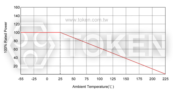
(HI83) - Derating Curve
|
(HI83) - Advance Non-Inductive Technique & Serpentine Pattern
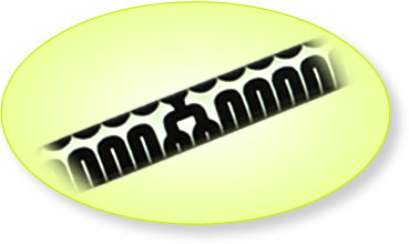
Non-Inductive Performance:
- HI83 Non-Inductive Design which uses a serpentine resistive pattern that offers for zigzagging lines to carry current in opposite directions, thereby achieving maximum neutralization of flux fields over the entire length of the resistor.
- This efficient non-inductive construction without derating of any performance advantages is ideal for applications where high frequency is required.
Serpentine Pattern Screen Printing Design:
- Type High Voltage HI83 Precision Resistors combine Token's Non-Inductive serpentine pattern, high thru-put screen printed silicone coating.
- The alignment of the gap in the serpentine resistor pattern with the gap in the coating pattern provides a complete encapsulation of the resistor element.
- The cap and lead assemblies are pressed onto the resistor core, finishing the resistor and providing rugged terminal attachment.
(HI83) - High Voltage Divider Application Notes
- Due to the high voltage that may occur between the terminals and any adjacent metal parts,
the voltage divider should be installed at a sufficient distance from other conductors. - For some ultra-high voltage applications, it is necessary to immerse the component in oil or SF6 gas
or place it in a void-free silicone compound to reduce surface tracking or corona.
The printed protection is right for these applications. - The planar voltage divider consists of high value R1 and low value R2.
The voltage division ratio of the divider is specified by Ratio R2: (R1 + R2).
(HI83) Thick Film Planar High Voltage Divider Resistors - Order Codes
Example:
HI83-20 for a voltage ratio of 1:1000, with R1 = 99.9 megohms and R2 = 100 kilohms (total R1 + R2 = 100 megohms)
at 50ppm/°C absolute and 25ppm/°C tracking TCR, 1% absolute and 0.5% ratio tolerance.
| HI83 | 20 | C2C3 | 100M | 100K | FD | ||||||||||||||||||||||||||||||||||||||||||||||||
 |
|
|
|
|
|
||||||||||||||||||||||||||||||||||||||||||||||||
|
|
|
|
|
|
||||||||||||||||||||||||||||||||||||||||||||||||