Precision High Voltage Resistors (RI82)
(RI82) High Voltage Precision Non-Inductive Resistors - Introduction
(RI82) An Excellent Solution for The High Voltage Trend in Power Impulse Precision Products


The High Voltage RI82 Precision Series provides an excellent solution for design engineers looking for a compact product with high-voltage capabilities to enable them to design within the voltage trend for power impulse products.
The RI82 resistors use Token's proprietary thick film Metal Glaze resistive element and Serpentine Pattern Design which provides ideal cost efficient, stability, precision, non-Inductive, and high voltage characteristics for a wide range of measurement, voltage divider circuits, and control functions in high voltage power electronics applications.
By utilizing specific 96 % pure alumina materials with optimum processing, Token are able to control, very tightly in manufacturing, the important ultra-stable performance tolerance F(±1%), G(±2%), J(±5%), K(±10%), and M(±20%). Voltage handle up to 30 KV.
This unique process is offered in specific resistance values in a wide variety of sizes and terminations. The extraordinary operating stability of the Type RI82 resistors will improve the performance of your high voltage system in precision.
The Precision RI82 High Voltage Series is RoHS compliant and lead free. For customed designs, tighter tolerances, non-standard technical requirements, or custom special applications, please contact our sales for more information.
Download complete specification Precision High Voltage Resistors (RI82) PDF.
- Resistance Tolerance F(±1%), G(±2%), J(±5%), K(±10%), and M(±20%).
- Stable cermet resistive element bonded to a high-purity alumina substrate.
- Rated Wattage from 0.1W to 30W, Max Working Voltage from 2KV to 30KV.
- Temperature Coefficient: 200 ppm/°C to 300 ppm/°C. Resistance Range: 10MΩ to 100GΩ.
- Designs built from customer supplied schematics, Tough epoxy-based coating and high voltage stability
- Energy research, and EMI/lightning supression,
- X-ray/imaging equipment, Capacitor crowbar circuits,
- Impulse voltage generators, Pulse modulators, Radar Pulse-forming networks,
- Applications include power supplies, High voltage snubber circuits, Arc furnace damping,
- Transformers and any application requiring operation within an environment where high voltages are used.
- Resistive Element: Thick film
- Substrate: 96 % pure alumina
- Encapsulation: Epoxy base, conformal coating (c style only)
- Terminals: Silver palladium pole, tin plated copper leads
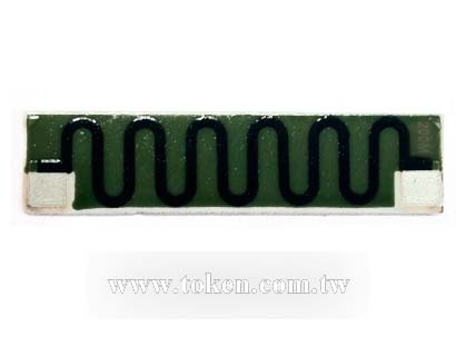
(RI82) Chip Type Specifications & Dimensions (Unit:mm)
(RI82) A Style Dimensions |
| ① | Silver Palladium Pole |
| ② | Resistent Film |
| ③ | Insulation Coating |
| ④ | Al2O3 Ceramic Base |
| Part Number |
Rated Wattage (w) |
Style | Dimensions (Unit:mm) | Resistance Range (Ω) |
Temp Coefficient (10-6/ °C) |
Resistance Tolerance |
Max Working Voltage (KV) |
||||
| Lmax | Smax | Hmax | I | dmax | |||||||
| RI82-2 | 2 | a | 33 | 8 | 0.8 | 10M-1T | ≤200 | J(±5%) K(±10%) M(±20%) |
15 | ||
| RI82-2 | 2 | a | 25 | 10 | 0.8 | ||||||
- Rated continuous Working Voltage (RCWV) shall be determined from RCWV =√ Power Rating × Resistance Value (Ω)
- When RCWV ≥ Max. Working Voltage listed above, RCWV = Max. Working Voltage.
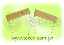
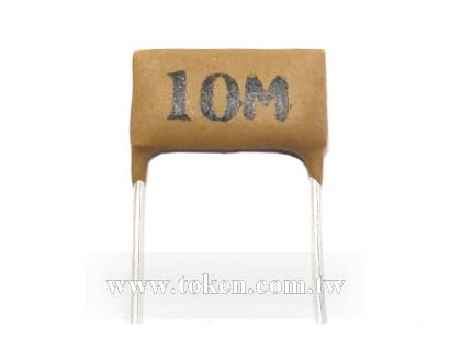
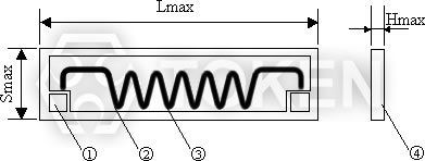
(RI82) Dip Type Specifications & Dimensions (Unit:mm)
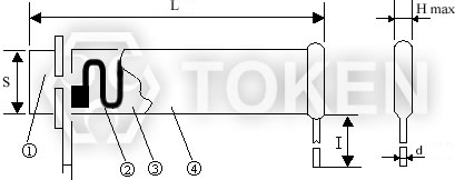
(RI82) B & C Style Dimensions |
| ① | Silver Palladium Pole |
| ② | Resistent Film |
| ③ | Insulation Coating (c style only) |
| ④ | Al2O3 Ceramic Base |
| Part Number |
Rated Wattage (w) |
Dimensions (Unit:mm) | Resistance Range (Ω) |
Temp Coefficient (10-6/°C) |
Max Working Voltage(KV) |
Resistance Tolerance |
||||
| L ± 2 | S ± 2 | H max | I | d ± 0.1 | ||||||
| RI82-0.125 | 0.125 | 8 | 3.5 | 2.5 | 20.0min | 0.56 | 100M-4.7G |
1R ≤ R < 1G,(±100PPM) 1G ≤ R < 10G,(±200PPM) 10G ≤ R < 100G,(±300PPM) 100G ≤ R ≤ 1T,(±500PPM) |
4 |
F(±1%) G(±2%) J(±5%) K(±10%) M(±20%) |
| RI82-0.125 | 0.125 | 10 | 5 | 2.5 | 24.0min | 0.56 | 100M-10G | 4 | ||
| RI82-0.25S | 0.25S | 10 | 5 | 2.5 | 20.0min | 0.56 | 10M-1T | 4 | ||
| RI82-0.25 | 0.25 | 22 | 4 | 2.5 | 20.0min | 0.56 | 100M-10G | 4 | ||
| RI82-0.25 | 0.25 | 25 | 5 | 2.5 | 20.0min | 0.56 | 100M-10G | 10 | ||
| RI82-0.5 | 0.5 | 35 | 5 | 2.5 | 24.0max | 0.56 | 100M-10G | 15 | ||
| RI82-0.5 | 0.5 | 41 | 5 | 2.5 | 42.0max | 0.56 | 10M-1T | 4 | ||
| RI82-1 | 1 | 25 | 10 | 2.5 | 30.0max | 0.56 | 100M-10G | 15 | ||
| RI82-1 | 1 | 30 | 8 | 2.5 | 30.0max | 0.8 | 100M-10G | 15 | ||
| RI82-1 | 1 | 33 | 8 | 2.5 | 35.0max | 0.56 | 100M-10G | 15 | ||
| RI82-1 | 1 | 38 | 10 | 3 | 45.0max | 0.80 | 100M-1T | 20 | ||
| RI82-2 | 2 | 38 | 10 | 3 | 40.0max | 0.80 | 100M-1T | 20 | ||
| RI82-2 | 2 | 45 | 10 | 3 | 45.0max | 0.80 | 100M-10G | 20 | ||
| RI82-3 | 3 | 50 | 10 | 3 | 45.0max | 0.80 | 100M-1T | 20 | ||
| RI82-3 | 3 | 30 | 15 | 3 | 35.0max | 0.80 | 100M-10G | 25 | ||
| RI82-3 | 3 | 60 | 10 | 3 | 55.0max | 0.80 | 100M-1T | 25 | ||
| RI82-5 | 5 | 80 | 20 | 4 | 60.0max | 0.80 | 100M-200M | 25 | ||
| RI82-10 | 10 | 97 | 23 | 4 | 80.0max | 0.80 | 100M-200M | 30 | ||
| RI82-20 | 20 | 100 | 35 | 4 | 80.0max | 1 | 100M-200M | 30 | ||
| RI82-30 | 30 | 100 | 48 | 4 | 80.0max | 1 | 100M-200M | 30 | ||
- Rated Continus Working Voltage (RCWW) shall be determined from RCWW =√ Power Rating × Resistance Value (Ω)
- or Max.Working Voltage listed above , whichever low.
(RI82) Advance Non-Inductive Technique & Serpentine Pattern
Non-Inductive Performance:
- Token's RI82 Non-Inductive Design which uses a serpentine resistive pattern that offers for zigzagging lines to carry current in opposite directions, thereby neutralizing maximum of flux fields over the entire length of the resistor.
- This efficient non-inductive construction retains performance advantages and heavy load characteristics which is ideal for high frequency applications.
Serpentine Pattern Screen Printing Design:
- Type RI82 High Voltage Impulse Resistors combine Token's Non-Inductive serpentine pattern, high thru-put screen printed silicone coating.
- The alignment of the gap in the serpentine resistor pattern with the gap in the coating pattern provides a complete encapsulation of the resistor element.
- The lead assemblies are pressed onto the resistor core, finishing the resistor and providing rugged terminal attachment.
(RI82) High-Voltage Non-Inductive Resistor - Order Codes
| RI82 | 0.125W | c | 47M | K | |||||||||||||||||||||||||||||||||
 |
|
|
|
|
|||||||||||||||||||||||||||||||||
|
|
|
|
|
|||||||||||||||||||||||||||||||||