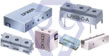
Dielectric Resonator Antenna and Filters
Microwave Dielectric Components


Dielectric Technology vs Saw Technology
| Table 1: Performance Comparison | ||||||
|---|---|---|---|---|---|---|
| Performance Comparison | Dielectric Filter (2GHz) | SAW Filter (2GHz) | ||||
| Insertion Loss | Low (>1.8dB) | Medium (>2.5dB) | ||||
| Fractional Band Width | Wide (<10%) | Medium (<3%) | ||||
| Frequency Range | Wide (<10G) | Medium (<3G) | ||||
| Spurious Response | Fair | Good | ||||
| Handling Power | High (<200W) | Low (<0.3W) | ||||
| IM (Inter-Modulation) | Excellent | Fair | ||||
| Temperature Performance | Stable (0~5ppm) | Unstable (-20~-90ppm) | ||||
| Impedance Matching | Good | Good | ||||
| Design flexibility | Good | Fair | ||||
| Size | Medium | Small | ||||
| Weight | Medium | Light | ||||
| Cost | Low | Medium | ||||
The technology comparison between dielectric filter and SAW filter is shown in Table 1. Items of comparison are electrical performances (insertion loss, fractional bandwidth, spurious response), handling power and intermodulation, size and weight, temperature stability, design flexibility, and cost (mass productivity).
SAW filter is superior in spurious response, size, weight, especially, but inferior in fractional bandwidth, frequency range and high handling power. On the other hand, dielectric filter is superior in insertion loss, fractional bandwidth, handling power, intermodulation and temperature performance, but inferior in spurious response, size, and weight. Those features are due to physical nature. As a result, each technology may be compensative with each other.
Commercially speaking, SAW is suitable for less than 1 GHz low power application, for example 900MHz band cellular handset filter. Dielectric filter is suitable for more than 2 GHz high power application, for example millimeter wave filter and cellular base station filter. But in overlapping region, for example 2GHz band handset filter, the method to gain the most practical and powerful solution must be combination and fusion of these technologies. Now what is required strongly for dielectric filter is the break through to the new technology suitable for combining with SAW technology.
As a candidate of novel dielectric technologies, planar filter utilizing thin film electrode is introduced. That may be coexisting and will be harmonized with SAW technology in the future. And dielectric technology will be growning up more than ever. Especially, for use of high power, wide band and high frequency operation, dielectric technology will be kept as the most powerful technology.
Download Dielectric Technology vs Saw Technology in PDF file.
Dielectric Terminology & Glossary
How Piezoceramic Element Works
When a piezoceramic element is stressed electrically by a voltage, its dimensions change. When it is stressed mechanically by a force, it generates an electric charge. If the electrodes are not short-circuited, a voltage associated with the charge appears.
- Relationships between applied forces and the resultant responses depend upon:
- the piezoelectric properties of the ceramic;
- the size and shape of the piece;
- and the direction of the electrical and mechanical excitation.
A piezoceramic is therefore capable of acting as either a sensing or transmitting element, or both. Since piezoceramic elements are capable of generating very high voltages, they are compatible with today's generation of solid-state devices - rugged, compact, reliable, and efficient.
Coaxial Resonator
A component in which standing waves are established in a ceramic coaxial line, short- or open-circuited at the end, remote from the drive. These resonators can be either 1/4 λ wavelength or 1/2 λ wavelength type.
Dielectric Dissipation Factor (tanδ)
The dielectric dissipation factor (dielectric loss factor), tanδ , for a ceramic material is the tangent of the dielectric loss angle. tanδ is determined by the ratio of effective conductance to effective susceptance in a parallel circuit, measured by using an impedance bridge. Values for tanδ typically are determined at 1 kHz.
Dielectric Resonator (DR)
An non-metallized dielectric ceramic which functions similarly to a mechanical resonant cavity at microwave frequencies, but has a greatly reduced size because of its high dielectric constant.
Dielectric Constant (K)
The relative dielectric constant is the ratio of the permittivity of the material, ε, to the permittivity of free space, ε0, in the unconstrained condition, i.e., well below the mechanical resonance of the part.
Equation: K = (permittivity of material ε / permittivity of free space ε0)
Global Positioning System (GPS)
A global navigation system based on 24 or more satellites orbiting the earth at an altitude of 12,000 statue miles and providing very precise, worldwide positioning and navigation information 24 hours a day, in any weather. Also called the NAVSTAR system.
Spurious Mode
Output from a dielectric resonator caused by a signal or signals having frequencies other than the resonant frequency desired. The presence of higher resonant modes close to the resonant frequency of the principle mode will interfere with filter or oscillator performance.
Voltage Standing Wave Ratio (VSWR)
The traditional way to determine the reflection coefficient is to measure the standing wave caused by the superposition of the incident wave and the reflected wave. Traditionally the voltage is measured at a series of points using a slotted line. The ratio of the maximum divided by the minimum is the Voltage Standing Wave Ratio (VSWR). The VSWR is infinite for total reflections because the minimum voltage is zero. If no reflection occurs the VSWR is 1.0. VSWR and reflection coefficient are related as follows:
Equation: VSWR = (1 + ρ) / (1 - ρ)
Quality Factor (Q = 1 / tanδ)
The figure of merit for assessing the performance or quality of a resonator, the Quality factor Q, is a measure of energy loss or dissipation per cycle as compared to the energy stored in the fields inside the resonator.
Catalogue Download
Download Dielectric Terminology & Glossary in PDF file.
Piezoelectric Charge Constant "d"
(Figure-1) - Directions of forces on piezoelectric element
The piezoelectric constants relating the mechanical strain produced by an applied electric field are termed the strain constants, or the "d" coefficients.
The units may then be expressed as meters per meter, per volts per meter (meters per volt).
Equation: d = (strain development / applied electric field)
It is useful to remember that large dij constants relate to large mechanical displacements which are usually sought in motional transducer devices. Conversely, the coefficient may be viewed as relating the charge collected on the electrodes, to the applied mechanical stress. d33 applies when the force is in the 3 direction (along the polarization axis) and is impressed on the same surface on which the charge is collected. d31 applies when the charge is collected on the same surface as before, but the force is applied at right angles to the polarization axis.
The subscripts in d15 indicate that the charge is collected on electrodes which are at right angles to the original poling electrodes and that the applied mechanical stress is shear. The units for the dij coefficients are commonly expressed as coulombs/square meter per newton/square meter.
Equation: d = (short circuit charge density / applied mechanical stress)
When the force that is applied is distributed over an area which is fully covered by electrodes (even if that is only a portion of the total electrode) the units of the area cancel from the equation and the coefficient may be expressed in terms of change per unit force, coulombs per newton. To view the dij coefficients in this manner is useful when charge generators are contemplated, e.g., accelerometers.
Piezoelectric Voltage Constant "g"
The piezoelectric constants relating the electric field produced by a mechanical stress are termed the voltage constants, or the "g" coefficients. The units may then be expressed as volts/meter per newtons/square meter.
Equation: g = (open circuit electric field / applied mechanical stress)
Output voltage is obtained by multiplying the calculated electric field by the thickness of ceramic between electrodes. A "33" subscript indicates that the electric field and the mechanical stress are both along the polarization axis. A "31" subscript signifies that the pressure is applied at right angles to the polarization axis, but the voltage appears on the same electrodes as in the "33" case.
A "15" subscript implies that the applied stress is shear and that the resulting electric field is perpendicular to the polarization axis. High gij constants favor large voltage output, and are sought after for sensors. Although the g coefficient are called voltage coefficients, it is also correct to say the gij is the ratio of strain developed over the applied charge density with units of meters per meter over coulombs per square meter.
(Figure-2) - Polarization of Dielectric
Polarization of Dielectric
If a material contains polar molecules, they will generally be in random orientations when no electric field is applied. An applied electric field will polarize the material by orienting the dipole moments of polar molecules.
This decreases the effective electric field between the plates and will increase the capacitance of the parallel plate structure. The dielectric must be a good electric insulator so as to minimize any DC leakage current through a capacitor.
General Information of Dielectric Microwave Components
Advantage of Token's Microwave Dielectric Components
New Microwave Dielectric Materials for Wireless Communication From Token Electronics
"Everything from the electromagnetic properties to microstructure of the material is important for the final result"
A small ceramic component made from a dielectric material is fundamental to the operation of filters and oscillators in several microwave systems, such as satellite TV receivers, military radar systems, Global Positioning System (GPS) devices, and mobile communications. Token Electronics had been able to develop specialized piezoelectric materials which lead to more reliable and clearer microwave communication signals.
In microwave communications, dielectric components are used to discriminate between wanted and unwanted signal frequencies in the transmitted and received signal. When the wanted frequency is extracted and detected it is necessary to maintain a strong signal nevertheless. For clarity it is also critical that the wanted signal frequencies are not affected by seasonal temperature changes.
The resonator materials for practical applications have to have certain key properties. A high relative dielectric constant is needed so that the materials can be miniaturised and a high quality factor (Q) is needed for improved selectivity. Low temperature variation of the material’s resonant frequency is also required so that the microwave circuits remain stable.
Although large numbers of ceramic dielectric materials have been developed, it has proven difficult to satisfy all these requirements in a single material at a reasonable cost. "Token takes the advantages of these new materials that they are relatively cheap compared with some of the compounds currently used and in the future they can be improved even further by suitable additives and by optimizing the preparation conditions."
Dielectric Material Composition & Study
The new dielectric materials developed by Token, are based on ceramics formed by baking the pressed powdered starting material mixture in a furnace at between 1200 and 1550 degrees Celsius.
Token Engineers used X-ray diffraction studies, Raman spectroscopy and scanning electron microscopy to reveal the structure of the ceramics. The materials have the general formula Ce(M1/2Ti1/2)O3.5. Ce is the element cerium, Ti is titanium and O is oxygen. "M" represents any one of the metals magnesium, zinc, calcium, cobalt, manganese, nickel or tungsten. The numbers refer to the proportions of each element in the ceramic.
"Further work is in progress to find the exact composition, internal structure and secondary phases in the ceramics".
Token's Service & PDF Catalogue Download
Toekn reliably deliver high-quality microwave dielectric components according to the each customer special needs with respect to performance, costs, and technology modifications.
For marketing discontinuations or sourcing activities concerning dielectric products, you are encouraged to contact our Sales Department so the request can be properly directed within Token.
Download General Info. of Dielectric in PDF file.
Download Microwave Dielectric Product Catalogue in PDF file .