Bandpass Filters (BP-R)
Dielectric Bandpass Filters (BP-R) Introduction
Dielectric Bandpass Filters (BP-R) Have a Low Ripple In Bandwidth 0.5 (dB) Max.
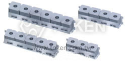
Dielectric bandpass filter, known as ceramic bandpass filter, dielectric ceramic filter, or microwave ceramic filter in standard resonator sizes. Token (BP-R) series center frequency range is from 915 MHz to 1220 MHz basic rules of ceramic band-pass filters and diplexer. Insertion loss is from 2.0 ~ 3.5 (dB) max and a ripple in bandwidth 0.5 (dB) max.
The higher the Q-factor of a resonators/band pass filters, the better electrical performance for insertion loss. The more dielectric resonators combined together for a band pass ceramic filters, the better rejection, attenuation, and stopband will be. Determinant factor for Insertion Loss Q factor of a resonator, the bandwidth of a filter, and the number of resonators Determinant factor for Attenuation/rejection The number of resonators, connection type of resonators.
Token (BP-R) RF filters can be customed designs and tighter tolerances available on request. Token (BP-R) series are primarily designed for high dielectric constant lines and conform to the RoHS directive.
The (BP-R) series feeature with high permittivity, high dielectric constants, extremely temperature stability and high Q that enables the design of stable microwave oscillators and filters. High dielectric constant (K) materials and associated products are also available for custom application requirements. Please contact our sales for more information.
Download Dielectric Bandpass Filters (BP-R) PDF Datasheet .
- Low insertion loss.
- Size small and light.
- High frequency selectivity.
- Temperature compensated.
- Trunked radio system.
- Cellular, cordless phone.
- Military affairs, Base station.
Dimensions (Unit: mm) (BP-R)
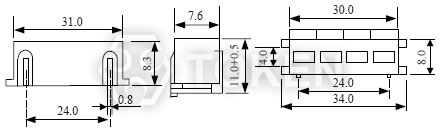
(BP-R) Dimensions |
Typical Specifications (BP-R)
| Part No. | Center Frequency (MHz) |
Band Width (MHz) |
Insertion Loss (dB)max. |
Ripple in BandWidth (dB)max. |
V.S.W.R max. |
Attenuation (dB)min.(MHz) |
| BP63R915-01 | 915 | fo±5 | 2.5 | 0.5 | 1.5 | 45 at fo±100 |
| BP64R881-02 | 881 | fo±10 | 2.0 | 0.5 | 2.0 | 60 at fo±100 |
| BP84R650-01 | 650 | fo±5 | 2.5 | 0.5 | 1.5 | 70 at fo±55 |
| BP84R1200-03 | 1200 | fo±15 | 2.0 | 0.5 | 2.0 | 70 at fo±60 |
| BP74R959-02 | 959 | fo±10 | 2.0 | 0.5 | 2.0 | 70 at fo±80 |
| BP75R836-01 | 836 | fo±5 | 3.5 | 0.5 | 1.5 | 80 at fo±50 |
| BP76R1220-02 | 1220 | fo±10 | 2.5 | 0.5 | 2.0 | 80 at fo±50 |
Order Codes (BP-R)
| BP | 3 | 4R | 1765 | - | 01 | ||||||||||||
 |
|
|
|
|
|||||||||||||
|
|
|
|
|
|||||||||||||