High current Round Edgewound Power Resistors
(DRE)Introduction (DRE)
High Current Round Edgewound Resistor (DRE)
Thumbnail GalleryToken coiling customer special round edgewound resistors fit renewable energy, load banks, dynamic braking, and inverters design
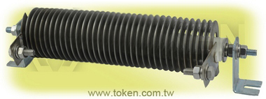
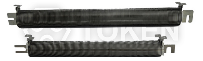
Token (DRE) Round Edgewound Resistor is a versatile, heavy-duty unit with lightweight construction, consisting of a non-corrodible, high quality stainless steel alloy. This tough resistor is appropriate for the following applications: VFD braking, motor control, load banks and neutral grounding applications.
(DRE) resistor includes through-rods, through-bars, fixed terminals, hardware and stainless steel element. It is supported by a mounting bar which is slotted at both end. Fixed terminations are made by welding stainless steel tabs to either end of the element, or at various points for multiple connections. The ribbon-like element is coiled on edge in the form of a helix, and then spun onto a porcelain core which a threaded rod passing through the center of the ceramic core.
Token (DRE) series is also available in many mounting configurations such as stud mount version, universal edgewound, mounting bracket options of Vishay, or Ohmite. Many standard hardware options allow resistors to be purchased fully assembled, allowing easy integration into the final assembly. Assemblies are wired in parallel or in series to meet the needs of the application. Terminal blocks and thermal switches are also available.
Value-add wiring and connectors allow for a "plug-and-play" solution that easily integrates into the final assembly. Custom resistors are designed to order by our engineers and can be customized to fit unique electrical and mechanical constraints.
Downloads complete PDF version (DRE) Power Round Edgewound High current Resistor. Contact us with your specific needs.
Customer special design options:
- Mechanical: Overall dimensions, mounting type, and configuration, insulation.
- Connection: Wire leads, connectors, terminal type, size, set-in, and material.
- Electrical: Tolerance, wattage, resistance, dielectric withstanding voltage, surge ability, temperature coefficient.
Features:
- Power Current from 5.1(A) to 105(A)
- Resistance nominal tolerance ±10%(K)
- Resistance value range 0.08Ω to 42.1#937;,
- suitable for high current applications
Applications:
- Power Industrial Machinery Resistors.
- Dynamic Braking Resistors, Load Banks, Motor Starting Resistor.
- Plugging Resistor, Electric Distribution Resistors.
- Wind Turbines, Harmonic Filters.
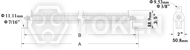
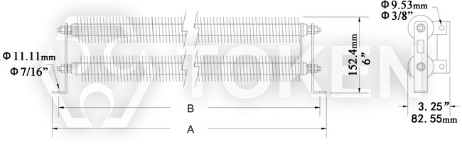
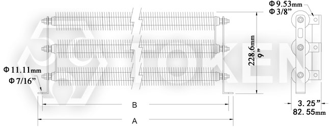
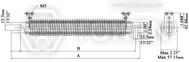
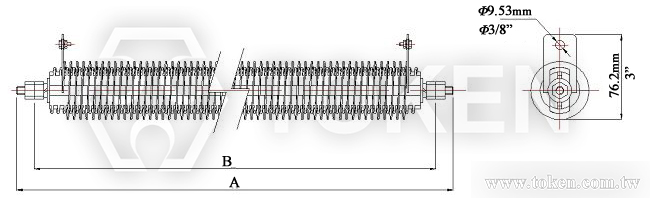
Round Edgewound Standard Dimensions ((DRE-P))
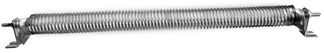
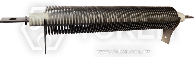
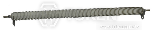
High power (DRE) series edge power resistors are constructed by coiling a resistance-alloy ribbon wire and winding it on edge over specially designed ceramic insulators. The porcelain insulators separate coils of the resistance elements from each other and the frame. The advantage is an open coil construction is to easily accommodate surges and overloads that allows efficient heat dissipation .
Round Edgewound Construction:
- Insulators provide insulation from threaded stud mount and proper turn-to-turn spacing.
- A sturdy welded steel frame supports the refractory insulators and finished with a zinc chromate conversion for corrosion resistance.
- The resistance element is a stainless steel strip with negligible temperature coefficient and anti-corrosion features,
used for its current carrying capacity vs Ohms per length. - The resistance element is designed by edgewinding a stainless strip into a continuous coil of the proper scaling length.
- Zinc plated terminals are welded to the resistive wire for a reliable electrical connection.
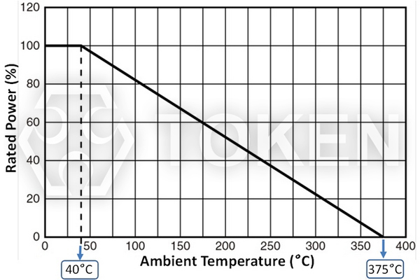
- •The continuous current ratings are based on a 375°C temperature rise.
- •The resistance values are measured at 25°C and have a ±10% tolerance.
|
||||||||||||||||||
Length Code | 2 | 3 | 4 | 5 | 6 | 7 | 8 | 9 | ||||||||||
Dimensions | mm | inch | mm | inch | mm | inch | mm | inch | mm | inch | mm | inch | mm | inch | mm | inch | ||
A | 228.6 | 9 | 285.75 | 11.25 | 381 | 15 | 438.15 | 17.25 | 615.95 | 24.25 | 615.95 | 24.25 | 762 | 30 | 838.2 | 33 | ||
B | 177.8 | 7 | 254.0 | 10 | 330.2 | 13 | 406.4 | 16 | 457.2 | 18 | 558.8 | 22 | 635 | 25 | 711.2 | 28 |
Edgewound Electrical Ratings (DRE-P)
Length Code | 2 | 3 | 4 | 5 | 6 | 7 | 8 | 9 |
Amps (A) | Resistance (Ω) at 25°C, Resistance Tolerance (10%) | |||||||
11 | 2.3 | 3.7 | 5.1 | 6.5 | 7.9 | 9.3 | 10.7 | 12.0 |
12 | 1.9 | 3.1 | 4.3 | 5.4 | 6.6 | 7.8 | 8.9 | 10.0 |
18 | 1.1 | 1.7 | 2.4 | 3.0 | 3.6 | 4.3 | 4.9 | 5.5 |
21 | 0.79 | 1.26 | 1.73 | 2.2 | 2.67 | 3.14 | 3.6 | 4.1 |
24 | 0.62 | 1.0 | 1.4 | 1.75 | 2.1 | 2.5 | 2.87 | 3.2 |
27 | 0.50 | 0.80 | 1.1 | 1.4 | 1.7 | 2.0 | 2.3 | 2.6 |
29 | 0.44 | 0.70 | 0.96 | 1.2 | 1.5 | 1.7 | 1.95 | 2.2 |
35 | 0.31 | 0.50 | 0.69 | 0.88 | 1.1 | 1.3 | 1.5 | 1.7 |
40 | 0.24 | 0.39 | 0.54 | 0.68 | 0.83 | 0.97 | 1.12 | 1.3 |
45 | 0.22 | 0.35 | 0.46 | 0.61 | 0.74 | 0.87 | 1.0 | 1.1 |
50 | 0.17 | 0.27 | 0.37 | 0.47 | 0.57 | 0.67 | 0.77 | 0.87 |
60 | - | 0.20 | 0.27 | 0.33 | 0.40 | 0.47 | 0.58 | 0.65 |
70 | - | 0.15 | 0.20 | 0.25 | 0.30 | 0.35 | 0.40 | 0.45 |
85 | - | 0.12 | 0.15 | 0.18 | 0.23 | 0.27 | 0.31 | 0.35 |
105 | - | 0.09 | 0.12 | 0.15 | 0.18 | 0.21 | 0.24 | 0.27 |
Round Edgewound Bracket Assembly Options Dimensions (DRE-G)
Fully assembled on open-style brackets are available in Token (DRE-G) Edgewound Resistor series. Mill galvanized brackets complete with all hardware and stainless steel bus bars with this open-style construction consist of resistors installed.
|
||||||||||||||||||||
Length Code | 2 | 3 | 4 | 5 | 6 | 7 | 8 | 9 | ||||||||||||
Dimensions | mm | inch | mm | inch | mm | inch | mm | inch | mm | inch | mm | inch | mm | inch | mm | inch | ||||
A | 228.6 | 9 | 304.8 | 12 | 381 | 15 | 457.2 | 18 | 508 | 20 | 609.6 | 24 | 685.8 | 27 | 762 | 30 | ||||
B | 203.2 | 8 | 579.4 | 11 | 355.6 | 14 | 431.8 | 17 | 482.6 | 19 | 584.2 | 23 | 660.4 | 26 | 736.6 | 29 |
|
Edgewound Electrical Ratings (DRE-G)
Length Code | 2 | 3 | 4 | 5 | 6 | 7 | 8 | 9 |
Amps (A) | Resistance (Ω) at 25°C, Resistance Tolerance (10%) | |||||||
11 | 2.3 | 3.7 | 5.1 | 6.5 | 7.9 | 9.3 | 10.7 | 12.0 |
12 | 1.9 | 3.1 | 4.3 | 5.4 | 6.6 | 7.8 | 8.9 | 10.0 |
18 | 1.1 | 1.7 | 2.4 | 3.0 | 3.6 | 4.3 | 4.9 | 5.5 |
21 | 0.79 | 1.26 | 1.73 | 2.2 | 2.67 | 3.14 | 3.6 | 4.1 |
24 | 0.62 | 1.0 | 1.4 | 1.75 | 2.1 | 2.5 | 2.87 | 3.2 |
27 | 0.50 | 0.80 | 1.1 | 1.4 | 1.7 | 2.0 | 2.3 | 2.6 |
29 | 0.44 | 0.70 | 0.96 | 1.2 | 1.5 | 1.7 | 1.95 | 2.2 |
35 | 0.31 | 0.50 | 0.69 | 0.88 | 1.1 | 1.3 | 1.5 | 1.7 |
40 | 0.24 | 0.39 | 0.54 | 0.68 | 0.83 | 0.97 | 1.12 | 1.3 |
45 | 0.22 | 0.35 | 0.46 | 0.61 | 0.74 | 0.87 | 1.0 | 1.1 |
50 | 0.17 | 0.27 | 0.37 | 0.47 | 0.57 | 0.67 | 0.77 | 0.87 |
60 | - | 0.20 | 0.27 | 0.33 | 0.40 | 0.47 | 0.58 | 0.65 |
70 | - | 0.15 | 0.20 | 0.25 | 0.30 | 0.35 | 0.40 | 0.45 |
85 | - | 0.12 | 0.15 | 0.18 | 0.23 | 0.27 | 0.31 | 0.35 |
105 | - | 0.09 | 0.12 | 0.15 | 0.18 | 0.21 | 0.24 | 0.27 |
|
Bar-Mount Edgewound Dimensions (DRE-R)
Token (DRE-R) bar-mounted edgewounds are existing with the same electrical ratings as the Type (DRE-G) edgewounds. All units have the same approximate diameter of 2 inches (50.8mm). Units are equipped with a through-bar and terminal hardware.
|
|||||||||||||||||||
Length Code | 2 | 3 | 4 | 5 | 6 | 7 | 8 | ||||||||||||
Dimensions | mm | inch | mm | inch | mm | inch | mm | inch | mm | inch | mm | inch | mm | inch | |||||
A | 225.43 | 8.875 | 301.63 | 11.875 | 377.83 | 14.875 | 454.03 | 17.875 | 530.23 | 20.875 | 606.43 | 23.875 | 682.63 | 26.875 | |||||
B | 184.15 | 7.25 | 260.35 | 10.25 | 336.55 | 13.25 | 412.75 | 16.25 | 488.95 | 19.25 | 565.15 | 22.25 | 641.35 | 25.256 |
Edgewound Electrical Ratings (DRE-R)
Length Code | 2 | 3 | 4 | 5 | 6 | 7 | 8 | |
Amps (A) | Resistance (Ω) at 25°C, Resistance Tolerance (10%) | |||||||
5.1 | 7.9 | 13.6 | 19.3 | 25.0 | 30.7 | 36.4 | 42.1 | |
5.9 | 6.3 | 10.9 | 15.4 | 20.0 | 24.5 | 29.0 | 33.5 | |
6.6 | 5.3 | 9.2 | 13.0 | 17.0 | 20.8 | 24.6 | 28.4 | |
7.6 | 4.1 | 7.1 | 10.0 | 13.0 | 15.9 | 18.8 | 21.7 | |
8.3 | 3.4 | 5.9 | 8.5 | 11.0 | 13.5 | 16.0 | 18.5 | |
9.4 | 2.70 | 4.60 | 6.50 | 8.50 | 10.4 | 12.3 | 14.2 | |
10.3 | 2.10 | 3.70 | 6.30 | 6.80 | 8.30 | 9.80 | 11.3 | |
11.8 | 1.70 | 2.90 | 4.20 | 5.40 | 6.60 | 7.80 | 9.00 | |
12.7 | 1.40 | 2.40 | 3.50 | 4.50 | 5.50 | 6.50 | 7.50 | |
14.6 | 1.10 | 1.90 | 2.70 | 3.50 | 4.30 | 5.10 | 5.90 | |
16.3 | 0.88 | 1.50 | 2.20 | 2.80 | 3.40 | 4.00 | 4.60 | |
18.4 | 0.69 | 1.20 | 1.70 | 2.20 | 2.70 | 3.10 | 3.50 | |
26 | 0.56 | 0.90 | 1.20 | 1.60 | 1.90 | 2.20 | 2.50 | |
29 | 0.45 | 0.73 | 1.00 | 1.30 | 1.50 | 1.75 | 2.00 | |
33 | 0.35 | 0.56 | 0.77 | 1.00 | 1.20 | 1.40 | 1.60 | |
39 | 0.26 | 0.42 | 0.58 | 0.75 | 0.90 | 1.05 | 1.20 | |
41 | 0.23 | 0.36 | 0.51 | 0.67 | 0.80 | 0.93 | 1.06 | |
43 | 0.21 | 0.33 | 0.46 | 0.60 | 0.72 | 0.85 | 0.98 | |
47 | 0.17 | 0.28 | 0.38 | 0.50 | 0.60 | 0.70 | 0.80 | |
50 | 0.12 | 0.20 | 0.28 | 0.37 | 0.45 | 0.53 | 0.61 | |
54 | 0.11 | 0.18 | 0.25 | 0.33 | 0.40 | 0.47 | 0.54 | |
57 | 0.10 | 0.16 | 0.23 | 0.30 | 0.36 | 0.42 | 0.48 | |
63 | 0.80 | 0.13 | 0.19 | 0.25 | 0.30 | 0.35 | 0.40 | |
68 | 0.07 | 0.12 | 0.18 | 0.22 | 0.26 | 0.30 | 0.34 | |
75 | 0.06 | 0.10 | 0.14 | 0.18 | 0.21 | 0.25 | 0.30 | |
78 | 0.052 | 0.088 | 0.12 | 0.16 | 0.16 | 0.22 | 0.25 | |
89 | 0.046 | 0.078 | 0.11 | 0.14 | 0.17 | 0.20 | 0.23 | |
91 | 0.040 | 0.070 | 0.10 | 0.12 | 0.14 | 0.16 | 0.18 | |
100 | 0.033 | 0.057 | 0.08 | 0.10 | 0.12 | 0.14 | 0.16 |
|
Electrical Characteristics (DRE)
Test Item | Specification | Test Methods |
Ambient Temperatures | Ambient Temperature: -55°C ~350°C. Derated current rating: 95% for 50°C ambient, 90% for 75°C ambient, 85% for 100°C ambient, 10% for 350°C ambient. |
Standard ratings are based on maximum ambient temperatures of 40°C. |
Continuous current ratings and temperatures Rise | 375°C Max. | The rating of continuous current is based on a 375°C temperature rise at ambient temperatures of 40°C. |
Resistance tolerance | Resistance Nominal Tolerance ±10%(K) for all units; as low as ±3% if required. |
JIS-C-5202 5-1 |
Thermal Shock | Δ≤±(2%R+0.1Ω) | JIS-C-5202 7.3, Room temp 30 minutes, -55°C 15 minutes. |
Terminal strength | Δ≤±(2%R+0.1Ω) | JIS-C-5202 6.1, 45N, 30S |
Short-term Overload | Δ≤±(2%R+0.1Ω) | JIS-C-5202 5.5, 10PR, 5S. |
|
Edgewound Derating Curve (DRE)
|
Order Codes (DRE)
DRE | 2 | 11 | 2R3 | K | G | |||||||||||||||||||||||||||||||||||||||||||||||||||||
1 | 2 | 3 | 4 | 5 | 6 | |||||||||||||||||||||||||||||||||||||||||||||||||||||
|
|
|
|
|
|