Chip Wire Wound Ceramic Inductors (TRWL)
Introduction (TRWL)
Token Wirewound Ceramic Inductor Simplifies Power Management Issues.
Token (TRWL) series is a wire wound and ceramic technology that offers the highest usable frequency range, highest current carrying capability, and the best Q factor of the three technologies. The combination of these three advantages ensure that design engineers will have the right product for many more high frequency applications than most competitors.
High frequency inductors are specifically used for their frequency dependent properties. Depending on the technology, size and inductance value, the inductor will pass a certain desired range of frequencies, but will block or attenuate frequencies above the desired range. This eliminates high frequency noise or interference from communications signals.
The Construction of Token (TRWL) open-type series chip wirewound ceramic inductors are designed to provide high SRFs. The full (TRWL) series conform to the RoHS directive and Lead-free. Customed designs and tighter tolerances are available on request.
Primarily, Token (TRWL) series as power inductors required by power supply circuits of multifunctional and small mobile phones must be small in size and low in height. These products must exhibit performance that is commensurate with the high power conversion efficiency of power supply circuits. Power supply circuits must also exhibit resistance to noise in the power supply state. All performance requirements of this component is expected based on the wire-wound inductors manufactured by Token.
Application of specific designs also available including different inductance values and Q specifications adjusted to frequency requirements. The (TRWL) series is supplied in tape and reel packaging ready for use with automated assembly processes. Contact us with your specific needs.
Download complete specification Chip Wire Wound Ceramic Inductors (TRWL) PDF.
- Tighter Tolerance of ±2%. Fully Automated Assembly.
- Smaller Size of 0402 (1005). Miniature ultra-compact size.
- High SRFs, exceptional Q values. Low profile, High Current are Available.
- CATV Filter, VCO, RF Module & Other Wireless Products.
- Cellular Phone (CDMA/GSM/PHS), Cordless Phone (DECT/CT1CT2).
- Remote Control, Security System, Wireless PDA. TCWLL, Wireless (LAN, Mouse, Keyboard,Earphone).
- Tunerk, Set Top Box, Base Station, Repeater GPS Receiver. USB 2.0, IEEE 1394, Cable Modem, XDSL Tuner.
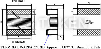
Configurations & Dimensions (Unit: mm) (TRWL)
Reel Dimensions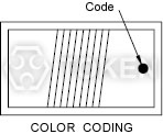
Tape Packing Dimensions |
||||||||||
| Type | A Max. |
B Max. |
C Max. |
D Ref. |
E | F | G | H | I | J |
| Standard --- | ||||||||||
| TRWL02 (EIA 0402) | 1.27 | 0.76 | 0.61 | 0.15 | 0.51 | 0.23 | 0.56 | 0.66 | 0.50 | 0.46 |
| TRWL03 (EIA 0603) | 1.80 | 1.12 | 1.02 | 0.38 | 0.76 | 0.33 | 0.86 | 1.02 | 0.64 | 0.64 |
| TRWL05 (EIA 0805) | 2.29 | 1.73 | 1.52 | 0.51 | 1.27 | 0.44 | 1.02 | 1.78 | 1.02 | 0.76 |
| TRWL06 (EIA 1206) | 3.56 | 2.16 | 1.52 | 0.50 | 1.20 | 0.50 | 2.20 | 1.93 | 1.02 | 1.78 |
| TRWL08 (EIA 1008) | 2.92 | 2.79 | 2.03 | 0.65 | 2.03 | 0.51 | 1.52 | 2.54 | 1.02 | 1.27 |
| Low Profile --- | ||||||||||
| TRWL05 (EIA 0805) | 2.29 | 1.73 | 1.03 | 0.51 | 1.27 | 0.44 | 1.02 | 1.78 | 1.02 | 0.76 |
| TRWL08 (EIA 1008) | 2.92 | 2.79 | 1.40 | 0.65 | 2.03 | 0.51 | 1.52 | 2.54 | 1.02 | 1.27 |
| High Current / High Q --- | ||||||||||
| TRWL03 (EIA 0603) | 1.80 | 1.12 | 1.02 | 0.38 | 0.76 | 0.33 | 0.86 | 1.02 | 0.64 | 0.64 |
| TRWL05 (EIA 0805) | 2.29 | 1.73 | 1.52 | 0.51 | 1.27 | 0.44 | 1.02 | 1.78 | 1.02 | 0.76 |
| TRWL08 (EIA 1008) | 2.92 | 2.79 | 2.03 | 0.65 | 2.03 | 0.51 | 1.52 | 2.54 | 1.02 | 1.27 |
- 0603 / 0805 / 1206 / 1008 Series (0402 Series is No Color Coding)
- Because of small sizes, these parts are marked with a single color dot. The inductance value represented by the dot is shown on the data page for each series.
Packaging Quantity & Reel Specifications (Unit: mm) (TRWL)
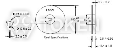
Packaging Quantity & Reel Specifications (TRWL)
|
Emboss Plastic Tape Specifications (Unit: mm)(TRWL)
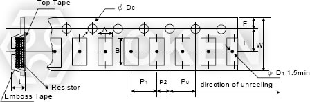
Emboss Plastic Tape Specifications (TRWL) |
||||||||||
| Codes | A ±0.10 |
B ±0.10 |
W ±0.2 |
E ±0.10 |
F ±0.1 |
P0 ±0.10 |
P1 ±0.10 |
P2 ±0.05 |
ΦD0 +0.10 |
t ±0.05 |
| TRWL08 | 2.70 | 2.80 | 8.0 | 1.75 | 3.5 | 4.00 | 4.00 | 2.00 | 1.50 | 2.00 |
| TRWL06 | 1.95 | 3.50 | 8.0 | 1.75 | 3.5 | 4.00 | 4.00 | 2.00 | 1.50 | 1.50 |
| TRWL05 | 1.85 | 2.30 | 8.0 | 1.75 | 3.5 | 4.00 | 4.00 | 2.00 | 1.50 | 1.45 |
| TRWL03 | 1.12 | 1.85 | 8.0 | 1.75 | 3.5 | 4.00 | 4.00 | 2.00 | 1.50 | 0.96 |
| TRWL02 | 0.71 | 1.16 | 8.0 | 1.75 | 3.5 | 4.00 | 2.00 | 2.00 | 1.50 | 0.65 |
| Item | Specification | Test Method |
| Vibration Test | Appearance: No damage L change: within ±5% Q change: within ±10% |
Test device shall be soldered on the substrate Oscillation Frequency: 10 to 55 to 10Hz for 1min Amplitude: 1.5mm Time: 2hrs for each axis (X, Y & Z), total 6hrs |
| Resistance to Soldering-Heat |
Solder Temperature: 260±5°C Immersion Time: 10±2sec |
|
| Component Adhesion (Push Test) |
1 lbs. For 0402 2 lbs. For 0603 3 lbs. For the rest |
The device should be soldered (260±5°C for 10 seconds) to a tinned copper subs rate. A dynamiter force gauge should be applied to the side of the component. The device must with stand a minimum force of 2 or 4 pounds without a failure of adhesion on termination |
| Drop Test | No damage | Dropping chip by each side and each corner. Drop 10 times in total Drop height: 100cm Drop weight: 125g |
| Solderability Test | 90% covered with solder. | Inductor shall be dipped in a melted solder bath at 235±5°C for 5 seconds. |
| Resistance to Solvent Test | No damage on appearance and marking. | MIL-STD202F, Method 215D |
Electrical Performance Test (TRWL)
| Item | Specification | Test Method |
| Inductance | Refer to standard electrical characteristic spec. | HP4291B |
| Q | HP4291B | |
| SRF | HP8753D | |
| DC Resistance RDC | Micro-Ohm meter (Gom-801G) | |
| Rated Current IDC | Applied the current to coils, The inductance change should be less than 10% to initial value | |
| Over Load Test | Inductors shall have no evidence of electrical and mechanical damage | Applied 2 times of rated allowed DC current to inductor for a period of 5 minute |
| Withstanding Voltage Test | Inductors shall be no evidence of electrical and mechanical damage. | AC voltage of 500 VAC applied between inductors terminal and case for 1 minute. |
| Insulation Resistance Test | 1000M ohm min | 100 VDC applied between inductor terminal and case |
Climatic Test (TRWL)
| Item | Specification | Test Method | ||||||||||||||
| Temperature Characteristic |
Appearance: No damage L change: within ±10% Q change: within ±20% |
-40°C~+125°C | ||||||||||||||
| Humidity Resistance | Temperature: 40±2°C Relative Humidity: 90~95% Time: 96hrs±2hrs Measured after exposure in the room condition for 2hrs |
|||||||||||||||
| Low Temperature Storage Test | Temperature: -40±2°C Time: 48±2hrs Inductors are tested after 1 hour at room temperature |
|||||||||||||||
| Thermal Shock Test | One cycle:
|
|||||||||||||||
| High Temperature Storage Test | Temperature: 125±2°C Time: 48±2hrs Measured after exposure in the room condition for 1hr |
|||||||||||||||
| High Temperature Load Life Test | There should be no evidence of short of open circuit. | Temperature: 85±2°C Time: 1000±12hrs Load: Allowed DC current |
||||||||||||||
| Humidity Load Life | Temperature: 40±2°C Relative Humidity: 90~95% Time: 1000±12hrs Load: Allowed DC current |
| Note: Storage Temperature: 25±3°C; Humidity: <80%RH |
Order Codes (TRWL)
| TRWL | 03 | J | T | S | 1N6 | S | ||||||||||||||||||||||||||||||||||||||||||||||||||||||||||||
 |
|
|
|
|
|
|
||||||||||||||||||||||||||||||||||||||||||||||||||||||||||||
|
|
|
|
|
|
|
||||||||||||||||||||||||||||||||||||||||||||||||||||||||||||