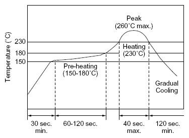
Ceramic Filters & Resonators Applications and Precautions

Chip Type Resonator Soldering Conditions

Reflow Solderings
Reflow Solderings of Chip Type Ceramic Resonator

Reflow
One heat stress, shown in the profile at right, is applied to resonator, then after being placed in natural conditions for 1 hour, the resonator is measured.

  • Pre-heating conditions should be +150 to +180°C for 60 to 120 seconds. Ascending time up to +150°C should be longer than 30 seconds.
  • Heating conditions should be within 40 seconds at +230°C min., but peak temperature should be lower than +260°C.

Soldering Iron
Soldering iron of +300±5°C should be placed 0.5mm above electrode of resonator. Melting solder through soldering iron should be applied to electrode for 3±1 seconds; then, after being placed in natural conditions for 24 hour, the resonator should be measured.

Wash

Please contact us in case you need washable component.

Notice for Mounting

  • The component is recommended for use with placement machines which employ optical placement capabilities.
  • The component might be damaged by excessive mechanical force. Please make sure to evaluate by using placement machines before going into mass production.
  • Do not use placement machines which utilize mechanical positioning. Please contact Token for details beforehand.
  • Please insure the component is thoroughly evaluated in your application circuit.
  • Please do not apply excess mechanical stress to the component and terminals during soldering.

Notice (Lead type Resonator Soldering and Mounting)

The component cannot withstand washing. Please do not apply excessive mechanical stress to the component and lead terminals during soldering.

Notice (Lead type Resonator Storage and Operating Conditions)

Product Storage Condition
Please store the products in room where the temperature/humidity is stable. And avoid such places where there are large temperature changes. Please store the products under the following conditions:

  • Temperature: -10 to + 40 °C
  • Humidity: 15 to 85% R.H.

Notice on Product Storage

  • Please do not store the products in a chemical atmosphere (Acids, Alkali, Bases, Organic gas, Sulfides and so on), because the characteristics may be reduced in quality, and/or be degraded in the solderability due to the storage in a chemical atmosphere.
  • Please do not put the products directly on the floor without anything under them to avoid damp places and/or dusty places.
  • Please do not store the products in the places such as: in a damp heated place, in a place where direct sunlight comes in, in place applying vibrations.
  • Please use the products immediately after the package is opened, because the characteristics may be reduced in quality, and/or be degraded in the solderability due to storage under the poor condition.
  • Please do not drop the products to avoid cracking of ceramic element.

Expire Date on Storage
Expire date (Shelf life) of the products is 3 months after delivery under the conditions of a sealed and an unopened package. Please use the products within 3 months after delivery. If you store the products for a long time (more than 3 months), use carefully because the products may be degraded in the solderability and/or rusty. Please confirm solderability and characteristics for the products regularly.

Others
Conformal coating or washing of the component is not acceptable because it is not hermetically sealed. Please be sure to consult with our sales representative or engineer whenever and prior to using the products.

Notice (Lead type Resonator Rating)

The component may be damaged if excess mechanical stress is applied.

Notice (Lead type Resonator Handling)

Piezo ceramic may stop oscillating or oscillate irregularly under improper circuit conditions.
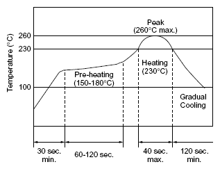
Chip Ceramic Filter Standard Reflow Soldering Conditions

Chip Ceramic Filter Reflow Soldering
Reflow Soldering of Chip Ceramic Filter

Reflow
Filter is soldered twice within the following temperature conditions.

Soldering Iron
Filter is soldered at +350±5°C for 3.0±0.5 seconds. The soldering iron should not touch the filter while soldering.

Chip Ceramic Filter Wash

The component cannot withstand washing.

Notice for Chip Ceramic Filter Handling

  • The component will be damaged when an excessive stress is applied.
  • The component may be damaged if excess mechanical stress is applied to it mounted on the printed circuit board.
  • Design layout of components on the PC board to minimize the stress imposed on the warp or flexure of the board.

---

  • After installing chips, if solder is excessively applied to the circuit board, mechanical stress will cause destruction resistance characteristics to lower. To prevent this, be extremely careful in determining shape and dimension before designing the circuit board diagram.
  • The component may be damaged during mounting process if some part of mounter such as positioning claws or nozzle are worn down. The regular maintenance recommended for mounters should be done to prevent troubles.
  • The component is recommended with placement machines which employ optical placement capabilities. The component might be damaged by excessive mechanical force. Please make sure that you have evaluated by using placement machines before going into mass production. Do not use placement machines which utilize mechanical positioning. Please contact Token for details beforehand.
  • When correcting chips with a soldering iron, the tip of the soldering iron should not directly touch the chip component. Depending on the soldering conditions, the effective area of terminations may be reduced. The use of solder containing Ag should be done to prevent the electrode erosion.
  • Do not clean or wash the component as it is not hermetically sealed.
  • In case of covering filter with over coat, conditions such as material of resin, cure temperature, and so on should be evaluated carefully.
  • Do not use strong acidity flux, more than 0.2wt% chlorine content, in re-flow soldering.
  • Accurate test circuit values are required to measure electrical characteristics. It may be a cause of miscorrelation if there is any deviation, especially stray capacitance, from the test circuit in the specification.
  • To avoid reliability degradation caused by thermal stress, when unpacked, store the component in an atmosphere at 30°C and below 60%R.H., and solder within 1 week.
  • For safety purposes, connect the output of filters to the IF amplifier through a D.C. blocking capacitor. Avoid applying a direct current to the output of ceramic filters.

Notice for Lead Type Ceramic Filter Handling

  • All kinds of re-flow soldering must not be applied on the component.
  • The component may be damaged when an excessive stress is applied.
  • Do not clean or wash the component as it is not hermetically sealed.
  • Do not use strong acidity flux, more than 0.2wt% chlorine content, in flow soldering.
  • Do not use this product with bend. The component may be damaged if excess mechanical stress is applied to it mounted on the printed circuit board.
  • In case of covering discriminator with over coat, conditions such as material of resin, cure temperature, and so on should be evaluated carefully.
  • Accurate test circuit values are required to measure electrical characteristics. It may be a cause of miscorrelation if there is any deviation, especially stray capacitance, from the test circuit in the specification.
  • For safety purposes, avoid applying a direct current between the terminals.

PDF Catalogue

Download Precautions of Ceramic Filters & Resonators in PDF file.