Surface acoustic wave propagates to the right and to the left because of IDT's symmetrical construction. Silicon rubber is coated on the outer side of IDT's to damp the surface acoustic wave propagates to outer side.
Maximum IDT finger overlap length.
Weighting produced by the change of finger overlap.
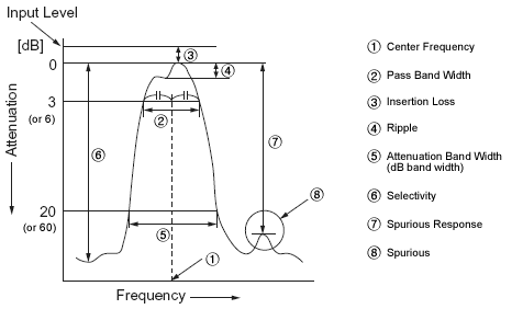
Signifies a difference between the two frequencies where the attenuation becomes the specified values (dB) from the level of minimum loss. (Example: Expressed at a point where the attenuation becomes 20 dB in case of 10.7 MHz filter.)
Signifies the minimum or average attenuation without both main response and spurious within the specified frequency range.
Unwanted signals caused by bulk wave excitation, which can be suppressed by grooving the bottom of the substrate.
A common electrode connecting individual fingers together.

It signifies the frequency in the center of the pass band width. However, the center frequency for some product is expressed at the point where the loss is minimum.
Ceramic Filter is a filter which uses a piezoelectric ceramics (barium titanate ceramics, lead-zirconate-titanate ceramics, etc.) as an electrical-mechanical transducer and as a mechanical resonator. It provides simultaneously the electrical and the mechanical system within a single element.
A ceramic resonator is an electronic component that when combined with other appropriate components, can produce oscillations at a specific frequency.
It consists of a voltage-variable capacitor that acts in some ways like a quartz crystal. Ceramic resonators are made of high-stability piezoelectric ceramics, generally lead zirconium titanate (PZT) which functions as a mechanical resonator.
When voltage is applied, its piezoelectric "vibration behavior" causes an oscillating signal. The thickness of the ceramic substrate determines the resonance frequency of the device.
Unwanted signals from the input appearing at the filter output due to coupling by stray capacitances and other electromagnetic couplings.
Decibel is the logarithmic ratio value by comparing the two levels. It is also used with ceramic filter when expressing the frequency characteristics, the insertion loss, the spurious response, etc. dB is defined and calculated by the ratio of the electric power, the voltage and the current, as follows:
The dB has been used only for comparing the two volumes such as the electric power ratio, voltage ratio, current ratio, etc. Besides dB may be also used for expressing the electric power or voltage by deciding on some reference values.
In ceramic filter, dBμ is used for expressing voltage value such as the input level. Here the reference value is 0 dBμ = 1 μV. In other words, the volume that represents a level of 60 dBμ equals 1 mV. It is important to clearly distinguish dB from dBμ.
The detection of FM wave is made through the circuit in which the relation between the frequency and the output voltage is linear. The discriminator functions to convert the change of the frequency into audio frequency, an unique system of detection only used for FM broadcasting. FM wave detection methods, such as ratio detection, Foster-Seeley detection, quadrature detection, differential peak detection, etc. are known.
An electrical component which has a function of passing (or stopping) a specific frequency.
An element of the IDT comb electrode.
The length of a finger pair between which only electromechanical interaction is generated.
One of the most important characteristics of a transmitting element is to transmit a signal with the lowest distortion. This distortion occurs when the phase shifting of a signal which passes through a certain transmitting path is nonlinear to the frequency.
For convenience the GDT characteristic is used for the purpose of expressing the non-linearity against the frequency of phase shifting and it is calculated by the following formula : TD (GDT), φ (phase difference between input and output) and ω (angular frequency).
TD = dφ / dω
Above formula shows that the phase slope was differentiated by the frequency. That is to say, when the GDT is constant, a signal is transmitted correctly without distortion. Recent trends in quality FM receiver and other equipment emphasizing the distortion factor characteristic are also stressing the phase linearity in the pass band.
In other word, they need a flat GDT Characteristic with high selectivity. In principle the GDT characteristic and the amplitude characteristic related each other.
The amplitude characteristic with a flat top is called the Butterworth Characteristic, while the amplitude characteristic resembling a sign wave is called a Gaussian Characteristic.
A comb structure consisting of interleaved metal electrodes whose function is to transform electrical energy into acoustic energy or vice versa by means of the piezoelectric effect.
When connecting one electric circuit to another, or a component to another, or one electric circuit to a component, the electric energy is supplied most efficiently from the signal source to the load if the signal source impedance and the load impedance are same.
If these impedances are mismatched, electric energy escapes in form of a reflection. To match the signal source impedance and the load impedance is called the impedance matching. This is very important for ceramic filter, as an improper impedance matching may cause various troubles.
Signifies the internal impedance value of the input and output side at the center frequency of ceramic filter, and it is expressed in Ω. It causes no problem even if the input and the output are used in reverse with ceramic filter, since the input and the output impedance are in a symmetry of substantially almost same value.
Expressed in the input and output level ratio at the point of minimum loss in dB. (The insertion loss for some product is expressed in the input and output level ratio at the center frequency.)
Signifies a difference between the two frequencies where the attenuation becomes 3dB from the level of the minimum loss point.

Distortion takes place in the crystal lattice when a stress is applied upon it, and the crystal group which has no symmetric center in the crystal groups causes a polarization in addition to the distortion.
This phenomenon was found by the Curie brothers in 1880 and is called the piezoelectric direct effect (or Curie’s Effect). In other wards, it means that the mechanical force (stress) can be converted into an electrical signal (an electrical field) or the electrical signal into the mechanical force. These two phenomena are collectively called the piezoelectric effect, and any substance which has this nature is called the piezoelectric ceramics.
The crystal group, the symmetry of which is inferior among all crystals having the characteristic of the piezoelectricity, has a native limited volume of polarization before some electric field or stress is applied. This is called spontaneous polarization.
The crystal is distorted by a phenomenon like the thermal vibration of atoms according to the temperature change. The degree of the spontaneous polarization also changes according to the distortion of crystal and its variation appears as a potential difference. This is called the phenomenon of pyroelectricity.
On the other hand, when such a crystal is applied with an electric field, a distortion or a stress occurs. It is called the piezoelectric inverse effect (or Lippman’s Effect).
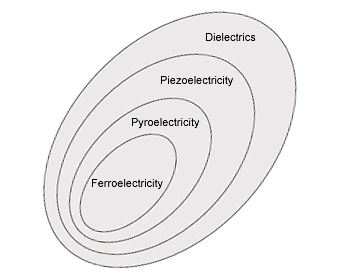
Also among the crystals which have a spontaneous polarization, those which can reverse its direction by the external electrical field are called ferroelectric substance. The relations among these effects may be expressed as figure on the right.
If there are peaks and valleys in a pass band width, the ripple expressed the level difference of voltage between the maximum peak and minimum valley and it is expressed in dB.
SAW electromechanical coupling coefficient defined by Ks2 = 2|ΔV/V|, which means the efficiency to transform electrical energy into acoustic energy or vice versa.
Expressed as the attenuation of the detuning point from the center frequency. (Example: The attenuation that ±9 kHz was detuned from the center frequency in case of 455 kHz filter.)
One of the ways expressing the selectivity, which is expressed as [Attenuation Band Width/Pass Band Width]. The selectivity becomes steeper as the resultant value comes closer to value 1.
Signifies the frequency response based on the parasitic (unwanted) vibration against the frequency except the fundamental vibration.
1~3 piezocomposites provide for significant advantages over solid piezoceramic transducers for ultrasound applications, at the expense of introduction of additional spurious resonances.
Expressed as the difference of voltage ratio between minimum attenuation point in the stop band range and minimum loss point in the pass band width by using dB (The stopped range is specified with each filter).
An acoustic wave, propagating along a surface of an elastic substrate, whose amplitude decays exponentially with substrate depth.
A filter characterized by a surface acoustic wave which is generated by IDT and propagates along a substrate surface to a receiving IDT.
Ceramic filter passes only particular frequency. To the contrary, Band Eliminate Filter (B. E. F.) which blocks or attenuates particular frequency is called trap. Sound trap for TV set is one of the famous example of B. E. F. In TV set, video signal is used in picture amplitude circuit after video signal detection block, ceramic resonator is insert here and trap circuit is formed in order to eliminate sound signal involved in video signal.
Unwanted signals in a SAW filter which has three times traversed the propagation path between input and output IDT's.