Photoresistor, CdS, Light Dependent Resistor LDR
Light Dependent Resistor


Typical application circuits
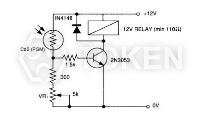
Figure 6 Sensitive light operated relay
Relay energised when light level increases above the level set by VR1
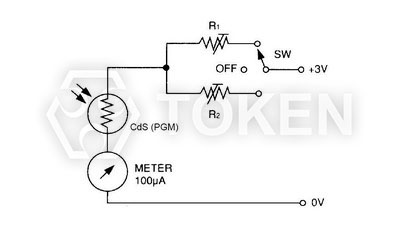
Figure 9 Logarithmic law photographic light meter
Typical value R1 = 100kΩ
R2 = 200kΩ preset to give two overlapping ranges.
(Calibration should be made against an accurate meter.)
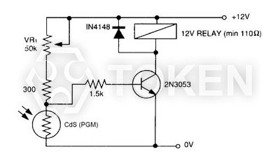
Figure 7 Light interruption detector
As Figure 6 relay energised when light level drops below the level set by VR1
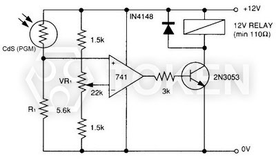
Figure 10 Extremely sensitive light operated relay
(Relay energised when light exceeds preset level.)
Incorporates a balancing bridge and op-amp. R1 and NORP12 may be interchanged for the reverse function.

Figure 8 Automatic light circuit
Adjust turn-on point with VR1
Light Dependent Resistors - General Information
How Does a CdS Photocell Work
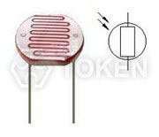
The right figure is a typical photoresistor LDR. It has two wire leads whose terminals are located on the surface of the photodetector - the two metal dots you see are the ends of these electrodes. The main body of the photodetector component is made of ceramic - an excellent insulator. On the surface of the ceramic, cadmium sulfide is coated with a serpentine pattern, so that the length of the strip is maximized while keeping the part smaller. Each end connected to the electrode, and then coated with a transparent epoxy resin.
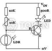
Figure 1: Photoresistor Basic Circuit
Activated from Darkness
Cadmium sulfide is a high-resistance semiconductor, selected as a photodetector, because it provides the same spectral response as the human eye - it see in response to the same wavelength that we can see. Specifically, cadmium sulfide is a photoconductive material. This means that with enough energy to hit the photons, the photons will release electrons from their atomic bonds.
When a negatively charged electron is released by a photon, it leaves a positively charged "hole". When a voltage is applied between the two leads of the photodetector, the free electrons move along the CdS band and the free "hole" moves to the other. This is the charge movement of the current through the photodetector. The higher the light intensity, the more photons hit the CdS band. Resulting in more electron-hole pairs, the more power can flow through the photodetector. So the lower the resistance of the photodetector (When the light intensity is high, the current through the photodetector is easier).
From the academic point of view - The conductivity of a semiconductor that is illuminated by illumination changes, or the phenomenon that produces a light electromotive force is called an internal photoelectric effect. The phenomenon that the conductivity of semiconductors is changed due to illumination is called photoconductive effect. The use of photoconductive effect of the principle of the components known as photoconductive detectors, and as a semiconductor material of a body effect. The stronger the light, the smaller the resistivity of the photoconductive material, so the photoconductive material is also called photoresistor.
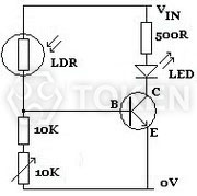
Figure 2: Photoresistor Basic Circuit
Activated by illumination
Photoresistor is an important part of the optical circuit, according to the intensity of ambient light automatically turn on and off the circuit. For example, solar garden lights and night safety lighting. LDR can even use a simple backlight remote control circuit to open the mobile phone device.
Different LDRs have different specifications. Token electronic production standard LDR (PGM) photoresistor, in the complete dark with MOhm resistance, in the bright light with KOhm resistance.
Photoresistor, CdS
Photoresistor and its circuit symbols
Light Dependent Resistor is also known as LDR, Cds, photoconductor, photoresistor or photovoltaic cells. There is a characteristic that decreases the resistance as the light intensity of the surface increases, and vice versa. Usually classified as resistors of electronic components. A typical photoresistor and its circuit symbols are shown on the right side of the figure.
Most LDRs are made from cadmium sulfide (CdS). They are very cheap, but the resistance range is wide. They are well suited for detecting changes in light levels and determining whether it is "dark" or "bright". However, if no single calibration, it is not suitable for accurate measurement of illumination level.
Photoresistor Basic Circuit
The basic circuit of the photosensitive resistor has two kinds, the first one is started in the dark, the second is started by illumination. These two circuits are very similar, requiring only one LDR, some standard resistors, a variable resistor (also known as potentiometer), and any small signal transistor.
In the basic circuit of the photoresistor Figure 1, the LED lights up whenever the LDR is in a dark state. The 10KOhm adjustable resistor is used to fine tune the dark levels required before the LED lights up. 10KOhm standard resistance can be changed according to actual needs to achieve the desired effect. But any replacement must have a resistance value of at least 1KOhm to protect the transistor from excessive current damage.
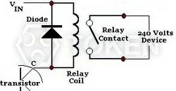
Figure 3: Low-Voltage Photodetection Circuit
By switching the LDR with a 10KOhm standard resistor and a 10KOhm adjustable resistor (as shown in Figure 2 of the basic circuit of the photoresistor). The circuit will be light-activated, when there is enough light to fall on the LDR, the LED will light (manually use 10KOhm adjustable resistance to fine-tune).
The two circuits shown above are not practical in the reality. In the actual circuit, the LED (and resistor) between the positive voltage input (Vin) and the collector (C) of the transistor will be replaced by the device to be powered.
Usually using relays, especially when the low voltage photodetector circuit is used to turn on (or turn off) the 240V power supply. A portion of this circuit is shown in the low-voltage photodetection circuit Figure 3. When the darkness drops (if the LDR circuit is configured as shown), the relay is triggered and the 240V device (eg safety light) is turned on.
Catalogue Download
Download Entire Light Sensors, Ambient Light Sensors in PDF file.