Miniature Low Profile Power Inductors (TPSME) Shielded
Introduction Preview
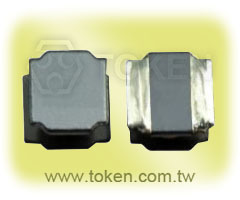
Token (TPSME) Miniature Low Profile Power Inductor for new generation portable products.
Token Electronics has added new ranges of low-profile wire wound chip inductors, TPSME201610, TPSME252010, TPSME252012,TPSME3010, TPSME3012, TPSME3015, TPSME4012, TPSME4018, TPSME4030, TPSME5020, TPSME6020, TPSME6028, TPSME6045, and TPSME8040, for use in DC-DC converter applications to increase flexibility of maximum height measurements with extended electrical characteristics.
The new TPSME series is designed to provide a good balance of height and performance within chip power miniature inductor offering. The TPSME201610, TPSME252010, and TPSME3010 Series were developed to have a low profile height of 1.0mm. The TPSME252012, TPSME3012, and TPSME4012 Series were developed to have a medium range maximum height of 1.2mm. Those TPSME family enables flexibility and efficiency.
All TPSME winding chip coils of inductors offer low DC resistance and large rated current. This is vital for DC-DC converter applications as it prevents energy dissipation from the chip inductor, improving the converter's overall efficiency.
The new ranges deliver a good size/performance ratio with low DC resistances of 0.010ohm (TPSME6045) and 0.025ohm (TPSME252012). A wide range of inductances is also available from 0.24μH to 330μH. The parts come with high rated currents, up to 15A, and feature magnetic shielding as standard. Operating temperature range is -55°C to +125°C.
Custom parts are available on request. Token will also produce devices outside these specifications to meet specific customer requirements, please contact our sales for more information.
Download Complete Datasheet Miniature Low Profile Power Inductors (TPSME) PDF.
- Low Profile: 1.0mm ~ 4.5mm.
- Excellent solderability and high heat resistance.
- High current (rated current): 0.34 to 15.0 amperes.
- GPS, CMMB, Digital photo Frame, telephone, CAR AV equipment.
- DC-DC converters, DVD, DSC, phone, PDA.
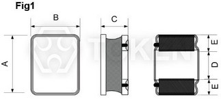
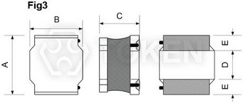
Dimensions & Configurations (Unit: mm) (TPSME)
   |
||||||
| Series | Dimensions (mm) | |||||
| A | B | C Max. |
D Ref. |
E Ref. |
Fig | |
| 201610 | 2.0 ± 0.2 | 1.6 ± 0.2 | 1.0 | 0.6 | 0.6 | Fig1/Fig2 |
| 252010 | 2.5 ± 0.2 | 2.0 ± 0.2 | 1.0 | 0.8 | 0.8 | Fig1 |
| 252012 | 2.5 ± 0.2 | 2.0 ± 0.2 | 1.2 | 0.8 | 0.8 | Fig1 |
| 3010 | 3.0 ± 0.2 | 3.0 ± 0.2 | 1.0 | 1.5 | 0.75 | Fig2 |
| 3012 | 3.0 ± 0.2 | 3.0 ± 0.2 | 1.2 | 1.5 | 0.75 | Fig2 |
| 3015 | 3.0 ± 0.2 | 3.0 ± 0.2 | 1.5 | 1.5 | 0.75 | Fig2 |
| 4012 | 4.0 ± 0.2 | 4.0 ± 0.2 | 1.2 | 2.1 | 0.95 | Fig2 |
| 4018 | 4.0 ± 0.2 | 4.0 ± 0.2 | 1.8 | 2.1 | 0.95 | Fig3 |
| 4030 | 4.0 ± 0.2 | 4.0 ± 0.2 | 3.0 | 2.1 | 0.95 | Fig3 |
| 5020 | 5.0 ± 0.2 | 5.0 ± 0.2 | 2.0 | 2.4 | 1.30 | Fig3 |
| 5040 | 5.0 ± 0.2 | 5.0 ± 0.2 | 4.0 | 2.4 | 1.30 | Fig2 |
| 6020 | 6.0 ± 0.5 | 6.0 ± 0.5 | 2.5 | 2.5 | 1.75 | Fig3 |
| 6028 | 6.0 ± 0.3 | 6.0 ± 0.3 | 3.3 | 2.5 | 1.75 | Fig3 |
| 6045 | 6.0 ± 0.2 | 6.0 ± 0.2 | 4.5 | 2.9 | 0.95 | Fig3 |
| 8040 | 8.0 ± 0.2 | 8.0 ± 0.2 | 4.0 | 4.0 | 1.6 | Fig2/Fig3 |
Electrical Specification (TPSME201610)
| Part Number | L (µH) | Tolerance (±%) | DCR (Ω) Max. | IDC Typ. (A) | |
| Heat Rating Current DC Amps. Idc (A) L↓30% | Saturation Current DC Amps. Isat (A) L↑40°C | ||||
| TPSME201610-R24M | 0.24 | 20 | 0.034 | 3.80 | 3.80 |
| TPSME201610-R33M | 0.33 | 20 | 0.052 | 3.70 | 3.50 |
| TPSME201610-R47M | 0.47 | 20 | 0.059 | 2.90 | 2.50 |
| TPSME201610-R68M | 0.68 | 20 | 0.078 | 2.20 | 2.40 |
| TPSME201610-1R0M | 1.00 | 20 | 0.104 | 1.90 | 2.00 |
| TPSME201610-2R2M | 2.20 | 20 | 0.120 | 1.00 | 1.40 |
| TPSME201610-4R7M | 4.70 | 20 | 0.396 | 0.90 | 1.00 |
| TPSME201610-100M | 10.00 | 20 | 0.956 | 0.70 | 0.70 |
Electrical Specification (TPSME201610 H Series)
| Part Number | L (µH) | Tolerance (±%) | DCR (Ω) Max. | IDC Typ. (A) | |
| Heat Rating Current DC Amps. Idc (A) L↓30% | Saturation Current DC Amps. Isat (A) L↑40°C | ||||
| TPSME201610HR24M | 0.24 | 20 | 0.032 | 4.20 | 4.30 |
| TPSME201610HR33M | 0.33 | 20 | 0.041 | 3.80 | 3.80 |
| TPSME201610HR47M | 0.47 | 20 | 0.059 | 2.90 | 2.50 |
| TPSME201610HR68M | 0.68 | 20 | 0.078 | 2.20 | 2.40 |
| TPSME201610H1R0M | 1.00 | 20 | 0.072 | 2.00 | 2.25 |
| TPSME201610H2R2M | 2.20 | 20 | 0.215 | 1.35 | 1.40 |
| TPSME201610H4R7M | 4.70 | 20 | 0.420 | 1.00 | 1.00 |
| TPSME201610H100M | 10.00 | 20 | 0.820 | 0.65 | 0.70 |
Electrical Specification (TPSME201610 E Series)
| Part Number | L (µH) | Tolerance (±%) | DCR (Ω) Max. | IDC Typ. (A) | |
| Heat Rating Current DC Amps. Idc (A) L↓30% | Saturation Current DC Amps. Isat (A) L↑40°C | ||||
| TPSME201610ER24M | 0.24 | 20 | 0.032 | 4.85 | 4.30 |
| TPSME201610ER47M | 0.47 | 20 | 0.042 | 3.60 | 3.00 |
| TPSME201610ER68M | 0.68 | 20 | 0.058 | 3.00 | 3.00 |
| TPSME201610E1R0M | 1.00 | 20 | 0.070 | 2.20 | 2.60 |
| TPSME201610E1R5M | 1.50 | 20 | 0.120 | 1.70 | 2.00 |
| TPSME201610E2R2M | 2.20 | 20 | 0.150 | 1.60 | 1.60 |
Electrical Specification (TPSME201610 A Series)
| Part Number | L (µH) | Tolerance (±%) | DCR (Ω) Max. | IDC Typ. (A) | |
| Heat Rating Current DC Amps. Idc (A) L↓30% | Saturation Current DC Amps. Isat (A) L↑40°C | ||||
| TPSME201610AR24M | 0.24 | 20 | 0.032 | 5.50 | 4.30 |
| TPSME201610AR33M | 0.33 | 20 | 0.032 | 4.60 | 3.80 |
| TPSME201610AR47M | 0.47 | 20 | 0.042 | 4.40 | 3.50 |
| TPSME201610AR68M | 0.68 | 20 | 0.057 | 3.40 | 3.00 |
| TPSME201610A1R0M | 1.00 | 20 | 0.090 | 3.15 | 2.40 |
| TPSME201610A1R5M | 1.50 | 20 | 0.130 | 2.20 | 2.00 |
| TPSME201610A2R2M | 2.20 | 20 | 0.165 | 2.10 | 1.45 |
Electrical Specification (TPSME201610 IH Series)
| Part Number | L (µH) | Tolerance (±%) | DCR (Ω) Max. | IDC Typ. (A) | |
| Heat Rating Current DC Amps. Idc (A) L↓30% | Saturation Current DC Amps. Isat (A) L↑40°C | ||||
| TPSME201610lHR24M | 0.24 | 20 | 0.026 | 7.00 | 4.50 |
| TPSME201610lHR33M | 0.33 | 20 | 0.029 | 6.00 | 4.00 |
| TPSME201610lHR47M | 0.47 | 20 | 0.036 | 4.50 | 3.80 |
| TPSME201610lHR68M | 0.68 | 20 | 0.050 | 4.00 | 3.10 |
| TPSME201610lH1R0M | 1.00 | 20 | 0.072 | 3.40 | 2.85 |
| TPSME201610lH1R5M | 1.50 | 20 | 0.120 | 2.20 | 2.10 |
| TPSME201610lH2R2M | 2.20 | 20 | 0.155 | 2.20 | 1.70 |
- The part temperature (ambient and temp rise) should not exceed 125°C under the worst case operating conditions.
- Part temperature should be verified in the application.
- Circuit Design, component placement, PWB trace size and thickness, airflow and other cooling provision all affect the part Temperature.
- The rated current as listed is either the saturation current or the heating current depending on which value is lower.
TPSME201610 All Series:
- All test data is referenced to 25°C ambient. Test condition: 100KHZ, 0.1Vrms.
- Irms: DC current(A) that will cause an approximate Δt of 40°C.
- Isat: DC current(A) that will cause L0 to drop approximately 30%.
- Operationg Temperature Range -55°C to +125°C.
Electrical Specification (TPSME252010)
| Part Number | L (µH) | Tolerance (±%) | DCR (Ω) Max. | IDC Typ. (A) | |
| Heat Rating Current DC Amps. Idc (A) L↓30% | Saturation Current DC Amps. Isat (A) L↑40°C | ||||
| TPSME252010-R47M | 0.47 | 20 | 0.056 | 3.40 | 2.70 |
| TPSME252010-R68M | 0.68 | 20 | 0.056 | 2.90 | 2.70 |
| TPSME252010-1R0M | 1.00 | 20 | 0.078 | 2.55 | 2.30 |
| TPSME252010-2R2M | 2.20 | 20 | 0.186 | 1.70 | 1.65 |
| TPSME252010-3R3M | 3.30 | 20 | 0.300 | 1.30 | 1.45 |
| TPSME252010-4R7M | 4.70 | 20 | 0.456 | 1.20 | 0.90 |
| TPSME252010-6R8M | 6.80 | 20 | 0.540 | 1.00 | 0.85 |
| TPSME252010-100M | 10.00 | 20 | 0.660 | 0.90 | 0.70 |
| TPSME252010-220M | 22.00 | 20 | 1.600 | 0.60 | 0.55 |
| TPSME252010-470M | 47.00 | 20 | 2.400 | 0.35 | 0.35 |
Electrical Specification (TPSME252010 H Series)
| Part Number | L (µH) | Tolerance (±%) | DCR (Ω) Max. | IDC Typ. (A) | |
| Heat Rating Current DC Amps. Idc (A) L↓30% | Saturation Current DC Amps. Isat (A) L↑40°C | ||||
| TPSME252010HR47M | 0.47 | 20 | 0.042 | 3.60 | 3.50 |
| TPSME252010HR68M | 0.68 | 20 | 0.058 | 3.20 | 3.20 |
| TPSME252010H1R0M | 1.00 | 20 | 0.072 | 2.70 | 2.70 |
| TPSME252010H2R2M | 2.20 | 20 | 0.142 | 1.70 | 1.75 |
| TPSME252010H3R3M | 3.30 | 20 | 1.50 | 1.50 | 1.25 |
Electrical Specification (TPSME252010 E Series)
| Part Number | L (µH) | Tolerance (±%) | DCR (Ω) Max. | IDC Typ. (A) | |
| Heat Rating Current DC Amps. Idc (A) L↓30% | Saturation Current DC Amps. Isat (A) L↑40°C | ||||
| TPSME252010ER24M | 0.24 | 20 | 0.030 | 5.50 | 4.30 |
| TPSME252010ER33M | 0.33 | 20 | 0.038 | 4.05 | 3.90 |
| TPSME252010ER47M | 0.47 | 20 | 0.038 | 3.90 | 3.90 |
| TPSME252010ER68M | 0.68 | 20 | 0.053 | 3.50 | 3.20 |
| TPSME252010E1R0M | 1.00 | 20 | 0.072 | 2.60 | 2.60 |
| TPSME252010E1R5M | 1.50 | 20 | 0.103 | 2.20 | 2.10 |
| TPSME252010E2R2M | 2.20 | 20 | 0.155 | 1.90 | 1.90 |
| TPSME252010E3R3M | 3.30 | 20 | 0.210 | 1.60 | 1.50 |
| TPSME252010E4R7M | 4.70 | 20 | 0.318 | 1.30 | 1.20 |
| TPSME252010E6R8M | 6.80 | 20 | 0.470 | 0.10 | 1.10 |
| TPSME252010E100M | 10.00 | 20 | 0.600 | 0.80 | 0.80 |
Electrical Specification (TPSME252010 A Series)
| Part Number | L (µH) | Tolerance (±%) | DCR (Ω) Max. | IDC Typ. (A) | |
| Heat Rating Current DC Amps. Idc (A) L↓30% | Saturation Current DC Amps. Isat (A) L↑40°C | ||||
| TPSME252010AR24M | 0.24 | 20 | 0.030 | 6.55 | 4.20 |
| TPSME252010AR33M | 0.33 | 20 | 0.026 | 6.50 | 5.00 |
| TPSME252010AR47M | 0.47 | 20 | 0.038 | 5.50 | 4.00 |
| TPSME252010AR68M | 0.68 | 20 | 0.050 | 4.15 | 3.90 |
| TPSME252010A1R0M | 1.00 | 20 | 0.065 | 3.55 | 3.00 |
| TPSME252010A1R5M | 1.50 | 20 | 0.100 | 3.00 | 2.35 |
| TPSME252010A2R2M | 2.20 | 20 | 0.130 | 2.30 | 2.00 |
| TPSME252010A4R7M | 4.70 | 20 | 0.310 | 1.60 | 1.35 |
Electrical Specification (TPSME252010 IH Series)
| Part Number | L (µH) | Tolerance (±%) | DCR (Ω) Max. | IDC Typ. (A) | |
| Heat Rating Current DC Amps. Idc (A) L↓30% | Saturation Current DC Amps. Isat (A) L↑40°C | ||||
| TPSME252010lHR24M | 0.24 | 20 | 0.018 | 8.90 | 6.50 |
| TPSME252010lHR33M | 0.33 | 20 | 0.024 | 7.50 | 5.50 |
| TPSME252010lHR47M | 0.47 | 20 | 0.030 | 6.50 | 4.70 |
| TPSME252010lHR68M | 0.68 | 20 | 0.040 | 5.60 | 4.20 |
| TPSME252010lH1R0M | 1.00 | 20 | 0.053 | 4.60 | 4.00 |
| TPSME252010lH1R5M | 1.50 | 20 | 0.075 | 3.80 | 3.30 |
| TPSME252010lH2R2M | 2.20 | 20 | 0.097 | 3.00 | 2.70 |
| TPSME252010lH4R7M | 4.70 | 20 | 0.250 | 1.70 | 1.50 |
Electrical Specification (TPSME252010 AH Series)
| Part Number | L (µH) | Tolerance (±%) | DCR (Ω) Max. | IDC Typ. (A) | |
| Heat Rating Current DC Amps. Idc (A) L↓30% | Saturation Current DC Amps. Isat (A) L↑40°C | ||||
| TPSME252010AHR24M | 0.24 | 20 | 0.027 | 7.10 | 4.60 |
| TPSME252010AHR33M | 0.33 | 20 | 0.027 | 5.30 | 4.40 |
| TPSME252010AHR47M | 0.47 | 20 | 0.035 | 6.00 | 4.50 |
| TPSME252010AHR68M | 0.68 | 20 | 0.045 | 4.70 | 4.00 |
| TPSME252010AH1R0M | 1.00 | 20 | 0.060 | 3.70 | 3.50 |
| TPSME252010AH1R5M | 1.50 | 20 | 0.085 | 3.00 | 2.90 |
| TPSME252010AH2R2M | 2.20 | 20 | 0.110 | 2.50 | 2.40 |
| TPSME252010AH4R7M | 4.70 | 20 | 0.276 | 1.70 | 1.35 |
- The part temperature (ambient and temp rise) should not exceed 125°C under the worst case operating conditions.
- Part temperature should be verified in the application.
- Circuit Design, component placement, PWB trace size and thickness, airflow and other cooling provision all affect the part Temperature.
- The rated current as listed is either the saturation current or the heating current depending on which value is lower.
TPSME252010 All Series:
- All test data is referenced to 25°C ambient. Test condition: 100KHZ, 0.1Vrms.
- Irms: DC current(A) that will cause an approximate Δt of 40°C.
- Isat: DC current(A) that will cause L0 to drop approximately 30%.
- Operationg Temperature Range -55°C to +125°C.
Electrical Specification (TPSME252012)
| Part Number | L (µH) | Tolerance (±%) | DCR (Ω) Max. | IDC Typ. (A) | |
| Heat Rating Current DC Amps. Idc (A) L↓30% | Saturation Current DC Amps. Isat (A) L↑40°C | ||||
| TPSME252012-R47M | 0.47 | 20 | 0.035 | 3.80 | 3.00 |
| TPSME252012-R68M | 0.68 | 20 | 0.048 | 3.00 | 2.50 |
| TPSME252012-1R0M | 1.00 | 20 | 0.065 | 2.60 | 2.43 |
| TPSME252012-1R5M | 1.50 | 20 | 0.088 | 1.80 | 1.95 |
| TPSME252012-2R2M | 2.20 | 20 | 0.144 | 1.55 | 1.70 |
| TPSME252012-3R3M | 3.30 | 20 | 0.174 | 1.30 | 1.35 |
| TPSME252012-4R7M | 4.70 | 20 | 0.252 | 1.25 | 1.12 |
| TPSME252012-6R8M | 6.80 | 20 | 0.360 | 0.90 | 0.85 |
| TPSME252012-100M | 10.00 | 20 | 0.600 | 0.75 | 0.70 |
| TPSME252012-220M | 22.00 | 20 | 1.150 | 0.50 | 0.50 |
Electrical Specification (TPSME252012 H Series)
| Part Number | L (µH) | Tolerance (±%) | DCR (Ω) Max. | IDC Typ. (A) | |
| Heat Rating Current DC Amps. Idc (A) L↓30% | Saturation Current DC Amps. Isat (A) L↑40°C | ||||
| TPSME252012HR33M | 0.33 | 20 | 0.030 | 5.05 | 5.25 |
| TPSME252012HR47M | 0.47 | 20 | 0.032 | 4.50 | 3.75 |
| TPSME252012HR68M | 0.68 | 20 | 0.042 | 3.90 | 3.50 |
| TPSME252012H1R0M | 1.00 | 20 | 0.056 | 3.00 | 3.50 |
| TPSME252012H2R2M | 2.20 | 20 | 0.100 | 1.90 | 2.20 |
| TPSME252012H3R3M | 3.30 | 20 | 0.144 | 1.70 | 1.60 |
| TPSME252012H4R7M | 4.70 | 20 | 0.216 | 1.40 | 1.35 |
| TPSME252012H6R8M | 6.80 | 20 | 0.300 | 1.20 | 1.05 |
| TPSME252012H100M | 10.00 | 20 | 0.462 | 1.00 | 0.90 |
Electrical Specification (TPSME252012 E Series)
| Part Number | L (µH) | Tolerance (±%) | DCR (Ω) Max. | IDC Typ. (A) | |
| Heat Rating Current DC Amps. Idc (A) L↓30% | Saturation Current DC Amps. Isat (A) L↑40°C | ||||
| TPSME252012ER24M | 0.24 | 20 | 0.025 | 5.00 | 4.30 |
| TPSME252012ER47M | 0.47 | 20 | 0.038 | 5.00 | 3.75 |
| TPSME252012ER68M | 0.68 | 20 | 0.045 | 4.10 | 3.60 |
| TPSME252012E1R0M | 1.00 | 20 | 0.054 | 3.50 | 3.50 |
| TPSME252012E1R5M | 1.50 | 20 | 0.072 | 2.50 | 2.25 |
| TPSME252012E2R2M | 2.20 | 20 | 0.105 | 2.30 | 2.40 |
Electrical Specification (TPSME252012 I Series)
| Part Number | L (µH) | Tolerance (±%) | DCR (Ω) Max. | IDC Typ. (A) | |
| Heat Rating Current DC Amps. Idc (A) L↓30% | Saturation Current DC Amps. Isat (A) L↑40°C | ||||
| TPSME252012lR24M | 0.24 | 20 | 0.025 | 5.00 | 4.30 |
| TPSME252012lR47M | 0.47 | 20 | 0.035 | 6.00 | 3.80 |
| TPSME252012lR68M | 0.68 | 20 | 0.045 | 4.80 | 3.80 |
| TPSME252012l1R0M | 1.00 | 20 | 0.057 | 4.00 | 3.60 |
| TPSME252012l1R5M | 1.50 | 20 | 0.095 | 4.00 | 3.00 |
| TPSME252012l2R2M | 2.20 | 20 | 0.100 | 3.00 | 2.40 |
- The part temperature (ambient and temp rise) should not exceed 125°C under the worst case operating conditions.
- Part temperature should be verified in the application.
- Circuit Design, component placement, PWB trace size and thickness, airflow and other cooling provision all affect the part Temperature.
- The rated current as listed is either the saturation current or the heating current depending on which value is lower.
TPSME252012 All Series:
- All test data is referenced to 25°C ambient. Test condition: 100KHZ, 0.1Vrms.
- Irms: DC current(A) that will cause an approximate Δt of 40°C.
- Isat: DC current(A) that will cause L0 to drop approximately 30%.
- Operationg Temperature Range -55°C to +125°C.
Electrical Specification (TPSME3010)
| Part Number | L (µH) | Tolerance (±%) | DCR (Ω) Max. | IDC Typ. (A) | |
| Heat Rating Current DC Amps. Idc (A) L↓30% | Saturation Current DC Amps. Isat (A) L↑40°C | ||||
| TPSME3010-R56M | 0.56 | 20 | 0.048 | 2.80 | 2.15 |
| TPSME3010-R68M | 0.68 | 20 | 0.048 | 2.50 | 2.15 |
| TPSME3010-1R0M | 1.00 | 20 | 0.066 | 2.15 | 2.00 |
| TPSME3010-1R5M | 1.50 | 20 | 0.078 | 1.65 | 1.70 |
| TPSME3010-2R2M | 2.20 | 20 | 0.096 | 1.35 | 1.55 |
| TPSME3010-3R3M | 3.30 | 20 | 0.145 | 1.20 | 1.25 |
| TPSME3010-4R7M | 4.70 | 20 | 0.222 | 1.10 | 1.05 |
| TPSME3010-6R8M | 6.80 | 20 | 0.330 | 0.85 | 0.70 |
| TPSME3010-8R2M | 8.20 | 20 | 0.348 | 0.80 | 0.80 |
| TPSME3010-100M | 10.00 | 20 | 0.480 | 0.70 | 0.70 |
| TPSME3010-150M | 15.00 | 20 | 0.624 | 0.60 | 0.60 |
| TPSME3010-220M | 22.00 | 20 | 1.000 | 0.50 | 0.50 |
| TPSME3010-330M | 10.00 | 20 | 0.480 | 0.70 | 0.70 |
- The part temperature (ambient and temp rise) should not exceed 125°C under the worst case operating conditions.
- Part temperature should be verified in the application.
- Circuit Design, component placement, PWB trace size and thickness, airflow and other cooling provision all affect the part Temperature.
- The rated current as listed is either the saturation current or the heating current depending on which value is lower.
TPSME252012 All Series:
- All test data is referenced to 25°C ambient. Test condition: 100KHZ, 0.1Vrms.
- Irms: DC current(A) that will cause an approximate Δt of 40°C.
- Isat: DC current(A) that will cause L0 to drop approximately 30%.
- Operationg Temperature Range -55°C to +125°C.
Electrical Specification (TPSME3012)
| Part Number | L (µH) | Tolerance (±%) | DCR (Ω) Max. | IDC Typ. (A) | |
| Heat Rating Current DC Amps. Idc (A) L↓30% | Saturation Current DC Amps. Isat (A) L↑40°C | ||||
| TPSME3012-R82M | 0.82 | 20 | 0.039 | 2.60 | 3.30 |
| TPSME3012-1R0M | 1.00 | 20 | 0.048 | 2.50 | 3.30 |
| TPSME3012-1R2M | 1.20 | 20 | 0.048 | 2.15 | 2.60 |
| TPSME3012-1R5M | 1.50 | 20 | 0.060 | 2.10 | 2.30 |
| TPSME3012-2R2M | 2.20 | 20 | 0.075 | 1.65 | 2.10 |
| TPSME3012-3R3M | 3.30 | 20 | 0.108 | 1.45 | 1.70 |
| TPSME3012-4R7M | 4.70 | 20 | 0.144 | 1.15 | 1.50 |
| TPSME3012-6R8M | 6.80 | 20 | 0.210 | 1.05 | 1.15 |
| TPSME3012-100M | 10.00 | 20 | 0.312 | 0.75 | 1.00 |
| TPSME3012-150M | 15.00 | 20 | 0.420 | 0.60 | 0.85 |
| TPSME3012-180M | 18.00 | 20 | 0.576 | 0.60 | 0.78 |
| TPSME3012-220M | 22.00 | 20 | 0.588 | 0.50 | 0.75 |
| TPSME3012-330M | 33.00 | 20 | 0.960 | 0.47 | 0.55 |
| TPSME3012-470M | 47.00 | 20 | 1.560 | 0.45 | 0.45 |
Electrical Specification (TPSME3012 I Series)
| Part Number | L (µH) | Tolerance (±%) | DCR (Ω) Max. | IDC Typ. (A) | |
| Heat Rating Current DC Amps. Idc (A) L↓30% | Saturation Current DC Amps. Isat (A) L↑40°C | ||||
| TPSME3012l1R0M | 1.00 | 20 | 0.055 | 6.00 | 3.10 |
| TPSME3012l2R2M | 2.20 | 20 | 0.108 | 3.35 | 2.35 |
| TPSME3012l4R7M | 4.70 | 20 | 0.235 | 2.50 | 1.50 |
| TPSME3012B100M | 10.00 | 20 | 0.415 | 1.10 | 0.90 |
| TPSME3012B220M | 22.00 | 20 | 0.800 | 0.75 | 0.70 |
- The part temperature (ambient and temp rise) should not exceed 125°C under the worst case operating conditions.
- Part temperature should be verified in the application.
- Circuit Design, component placement, PWB trace size and thickness, airflow and other cooling provision all affect the part Temperature.
- The rated current as listed is either the saturation current or the heating current depending on which value is lower.
TPSME3012 All Series:
- All test data is referenced to 25°C ambient. Test condition: 100KHZ, 0.1Vrms.
- Irms: DC current(A) that will cause an approximate Δt of 40°C.
- Isat: DC current(A) that will cause L0 to drop approximately 30%.
- Operationg Temperature Range -55°C to +125°C.
Electrical Specification (TPSME3015)
| Part Number | L (µH) | Tolerance (±%) | DCR (Ω) Max. | IDC Typ. (A) | |
| Heat Rating Current DC Amps. Idc (A) L↓30% | Saturation Current DC Amps. Isat (A) L↑40°C | ||||
| TPSME3015-1R0M | 1.00 | 20 | 0.040 | 2.80 | 2.85 |
| TPSME3015-1R2M | 1.20 | 20 | 0.048 | 2.80 | 2.65 |
| TPSME3015-1R5M | 1.50 | 20 | 0.055 | 2.75 | 2.60 |
| TPSME3015-2R2M | 2.20 | 20 | 0.072 | 2.10 | 2.25 |
| TPSME3015-3R3M | 3.30 | 20 | 0.102 | 1.75 | 1.85 |
| TPSME3015-3R9M | 3.90 | 20 | 0.132 | 1.50 | 1.70 |
| TPSME3015-4R7M | 4.70 | 20 | 0.145 | 1.45 | 1.50 |
| TPSME3015-5R6M | 5.60 | 20 | 0.156 | 1.20 | 1.50 |
| TPSME3015-6R8M | 6.80 | 20 | 0.200 | 1.15 | 1.30 |
| TPSME3015-8R2M | 8.20 | 20 | 0.228 | 1.05 | 1.20 |
| TPSME3015-100M | 10.00 | 20 | 0.300 | 1.10 | 1.05 |
| TPSME3015-120M | 12.00 | 20 | 0.300 | 0.85 | 1.05 |
| TPSME3015-150M | 15.00 | 20 | 0.420 | 0.80 | 0.95 |
| TPSME3015-220M | 22.00 | 20 | 0.545 | 0.65 | 0.85 |
| TPSME3015-330M | 33.00 | 20 | 0.852 | 0.50 | 0.65 |
| TPSME3015-470M | 47.00 | 20 | 1.200 | 0.45 | 0.55 |
| TPSME3015-680M | 68.00 | 20 | 2.400 | 0.34 | 0.40 |
- The part temperature (ambient and temp rise) should not exceed 125°C under the worst case operating conditions.
- Part temperature should be verified in the application.
- Circuit Design, component placement, PWB trace size and thickness, airflow and other cooling provision all affect the part Temperature.
- The rated current as listed is either the saturation current or the heating current depending on which value is lower.
TPSME3015 All Series:
- All test data is referenced to 25°C ambient. Test condition: 100KHZ, 0.1Vrms.
- Irms: DC current(A) that will cause an approximate Δt of 40°C.
- Isat: DC current(A) that will cause L0 to drop approximately 30%.
- Operationg Temperature Range -55°C to +125°C.
Electrical Specification (TPSME4012)
| Part Number | L (µH) | Tolerance (±%) | DCR (Ω) Max. | IDC Typ. (A) | |
| Heat Rating Current DC Amps. Idc (A) L↓30% | Saturation Current DC Amps. Isat (A) L↑40°C | ||||
| TPSME4012-R82M | 0.82 | 20 | 0.065 | 3.65 | 2.20 |
| TPSME4012-1R0M | 1.00 | 20 | 0.065 | 3.20 | 2.20 |
| TPSME4012-1R5M | 1.50 | 20 | 0.078 | 2.50 | 2.00 |
| TPSME4012-2R2M | 2.20 | 20 | 0.104 | 2.10 | 2.10 |
| TPSME4012-3R3M | 3.30 | 20 | 0.143 | 1.95 | 1.70 |
| TPSME4012-4R7M | 4.70 | 20 | 0.182 | 1.55 | 1.50 |
| TPSME4012-5R6M | 5.60 | 20 | 0.215 | 1.60 | 1.35 |
| TPSME4012-6R8M | 6.80 | 20 | 0.257 | 1.40 | 1.30 |
| TPSME4012-100M | 10.00 | 20 | 0.312 | 1.05 | 1.05 |
| TPSME4012-150M | 15.00 | 20 | 0.494 | 0.90 | 0.90 |
| TPSME4012-220M | 22.00 | 20 | 0.741 | 0.70 | 0.75 |
| TPSME4012-470M | 47.00 | 20 | 1.760 | 0.45 | 0.45 |
| TPSME4012-101M | 100.00 | 20 | 3.600 | 0.35 | 0.30 |
- The part temperature (ambient and temp rise) should not exceed 125°C under the worst case operating conditions.
- Part temperature should be verified in the application.
- Circuit Design, component placement, PWB trace size and thickness, airflow and other cooling provision all affect the part Temperature.
- The rated current as listed is either the saturation current or the heating current depending on which value is lower.
TPSME4012 All Series:
- All test data is referenced to 25°C ambient. Test condition: 100KHZ, 0.1Vrms.
- Irms: DC current(A) that will cause an approximate Δt of 40°C.
- Isat: DC current(A) that will cause L0 to drop approximately 30%.
- Operationg Temperature Range -55°C to +125°C.
Electrical Specification (TPSME4018)
| Part Number | L (µH) | Tolerance (±%) | DCR (Ω) Max. | IDC Typ. (A) | |
| Heat Rating Current DC Amps. Idc (A) L↓30% | Saturation Current DC Amps. Isat (A) L↑40°C | ||||
| TPSME4018-1R0M | 1.00 | 20 | 0.030 | 4.85 | 3.80 |
| TPSME4018-1R2M | 1.20 | 20 | 0.030 | 4.80 | 3.80 |
| TPSME4018-1R5M | 1.50 | 20 | 0.036 | 4.25 | 3.20 |
| TPSME4018-2R2M | 2.20 | 20 | 0.048 | 3.40 | 2.90 |
| TPSME4018-3R3M | 3.30 | 20 | 0.060 | 3.00 | 2.50 |
| TPSME4018-3R9M | 3.90 | 20 | 0.078 | 2.80 | 2.20 |
| TPSME4018-4R7M | 4.70 | 20 | 0.078 | 2.30 | 2.20 |
| TPSME4018-6R8M | 6.80 | 20 | 0.108 | 1.85 | 1.90 |
| TPSME4018-100M | 10.00 | 20 | 0.168 | 1.55 | 1.30 |
| TPSME4018-150M | 15.00 | 20 | 0.228 | 1.25 | 1.20 |
| TPSME4018-220M | 22.00 | 20 | 0.336 | 1.10 | 1.10 |
| TPSME4018-330M | 33.00 | 20 | 0.480 | 0.90 | 0.85 |
| TPSME4018-470M | 47.00 | 20 | 0.720 | 0.80 | 0.70 |
| TPSME4018-101M | 100.00 | 20 | 1.740 | 0.55 | 0.35 |
- The part temperature (ambient and temp rise) should not exceed 125°C under the worst case operating conditions.
- Part temperature should be verified in the application.
- Circuit Design, component placement, PWB trace size and thickness, airflow and other cooling provision all affect the part Temperature.
- The rated current as listed is either the saturation current or the heating current depending on which value is lower.
TPSME4018 All Series:
- All test data is referenced to 25°C ambient. Test condition: 100KHZ, 0.1Vrms.
- Irms: DC current(A) that will cause an approximate Δt of 40°C.
- Isat: DC current(A) that will cause L0 to drop approximately 30%.
- Operationg Temperature Range -55°C to +125°C.
Electrical Specification (TPSME4030)
| Part Number | L (µH) | Tolerance (±%) | DCR (Ω) Max. | IDC Typ. (A) | |
| Heat Rating Current DC Amps. Idc (A) L↓30% | Saturation Current DC Amps. Isat (A) L↑40°C | ||||
| TPSME4030-R91M | 0.91 | 20 | 0.029 | 7.30 | 3.50 |
| TPSME4030-1R0M | 1.00 | 20 | 0.034 | 6.50 | 3.30 |
| TPSME4030-1R2M | 1.20 | 20 | 0.038 | 6.00 | 3.25 |
| TPSME4030-1R5M | 1.50 | 20 | 0.039 | 5.50 | 3.20 |
| TPSME4030-2R2M | 2.20 | 20 | 0.046 | 4.70 | 2.85 |
| TPSME4030-3R3M | 3.30 | 20 | 0.052 | 3.70 | 2.65 |
| TPSME4030-4R7M | 4.70 | 20 | 0.078 | 3.20 | 2.20 |
| TPSME4030-6R8M | 6.80 | 20 | 0.109 | 2.80 | 1.80 |
| TPSME4030-100M | 10.00 | 20 | 0.125 | 2.20 | 1.65 |
| TPSME4030-120M | 12.00 | 20 | 0.170 | 2.10 | 1.45 |
| TPSME4030-150M | 15.00 | 20 | 0.245 | 1.90 | 1.20 |
| TPSME4030-220M | 22.00 | 20 | 0.295 | 1.50 | 1.10 |
| TPSME4030-330M | 33.00 | 20 | 0.415 | 1.30 | 0.95 |
| TPSME4030-390M | 39.00 | 20 | 0.450 | 1.10 | 0.90 |
| TPSME4030-470M | 47.00 | 20 | 0.580 | 1.05 | 0.80 |
| TPSME4030-560M | 56.00 | 20 | 0.720 | 0.95 | 0.70 |
| TPSME4030-620M | 62.00 | 20 | 1.080 | 0.85 | 0.60 |
| TPSME4030-680M | 68.00 | 20 | 1.130 | 0.85 | 0.55 |
| TPSME4030-101M | 100.00 | 20 | 1.450 | 0.75 | 0.50 |
| TPSME4030-121M | 120.00 | 20 | 1.630 | 0.60 | 0.47 |
| TPSME4030-151M | 150.00 | 20 | 1.720 | 0.60 | 0.46 |
| TPSME4030-331M | 330.00 | 20 | 4.080 | 0.38 | 0.30 |
- The part temperature (ambient and temp rise) should not exceed 125°C under the worst case operating conditions.
- Part temperature should be verified in the application.
- Circuit Design, component placement, PWB trace size and thickness, airflow and other cooling provision all affect the part Temperature.
- The rated current as listed is either the saturation current or the heating current depending on which value is lower.
TPSME4030 All Series:
- All test data is referenced to 25°C ambient. Test condition: 100KHZ, 0.1Vrms.
- Irms: DC current(A) that will cause an approximate Δt of 40°C.
- Isat: DC current(A) that will cause L0 to drop approximately 30%.
- Operationg Temperature Range -55°C to +125°C.
Electrical Specification (TPSME5020)
| Part Number | L (µH) | Tolerance (±%) | DCR (Ω) Max. | IDC Typ. (A) | |
| Heat Rating Current DC Amps. Idc (A) L↓30% | Saturation Current DC Amps. Isat (A) L↑40°C | ||||
| TPSME5020-R47M | 0.47 | 20 | 0.017 | 6.15 | 4.60 |
| TPSME5020-R75M | 0.75 | 20 | 0.022 | 5.50 | 4.00 |
| TPSME5020-1R0M | 1.00 | 20 | 0.026 | 4.10 | 3.80 |
| TPSME5020-1R2M | 1.20 | 20 | 0.029 | 4.50 | 3.55 |
| TPSME5020-1R5M | 1.50 | 20 | 0.034 | 4.10 | 3.20 |
| TPSME5020-2R2M | 2.20 | 20 | 0.042 | 3.20 | 2.90 |
| TPSME5020-2R7M | 2.70 | 20 | 0.049 | 2.90 | 2.70 |
| TPSME5020-3R0M | 3.00 | 20 | 0.049 | 2.55 | 2.70 |
| TPSME5020-3R3M | 3.30 | 20 | 0.056 | 2.55 | 2.50 |
| TPSME5020-3R6M | 3.60 | 20 | 0.056 | 2.80 | 2.50 |
| TPSME5020-3R9M | 3.90 | 20 | 0.056 | 2.30 | 2.50 |
| TPSME5020-4R3M | 4.30 | 20 | 0.074 | 2.50 | 2.20 |
| TPSME5020-4R7M | 4.70 | 20 | 0.074 | 2.50 | 2.20 |
| TPSME5020-5R1M | 5.10 | 20 | 0.083 | 2.25 | 2.05 |
| TPSME5020-5R6M | 5.60 | 20 | 0.083 | 2.30 | 2.05 |
| TPSME5020-6R8M | 6.80 | 20 | 0.108 | 2.05 | 1.80 |
| TPSME5020-7R5M | 7.50 | 20 | 0.117 | 1.85 | 1.75 |
| TPSME5020-8R2M | 8.20 | 20 | 0.127 | 1.85 | 1.65 |
| TPSME5020-9R1M | 9.10 | 20 | 0.143 | 1.70 | 1.55 |
| TPSME5020-100M | 10.00 | 20 | 0.143 | 1.70 | 1.55 |
| TPSME5020-120M | 12.00 | 20 | 0.182 | 1.50 | 1.40 |
| TPSME5020-150M | 15.00 | 20 | 0.215 | 1.35 | 1.25 |
| TPSME5020-180M | 18.00 | 20 | 0.260 | 1.25 | 1.15 |
| TPSME5020-220M | 22.00 | 20 | 0.294 | 1.15 | 1.10 |
- The part temperature (ambient and temp rise) should not exceed 125°C under the worst case operating conditions.
- Part temperature should be verified in the application.
- Circuit Design, component placement, PWB trace size and thickness, airflow and other cooling provision all affect the part Temperature.
- The rated current as listed is either the saturation current or the heating current depending on which value is lower.
TPSME5020 All Series:
- All test data is referenced to 25°C ambient. Test condition: 100KHZ, 0.1Vrms.
- Irms: DC current(A) that will cause an approximate Δt of 40°C.
- Isat: DC current(A) that will cause L0 to drop approximately 30%.
- Operationg Temperature Range -55°C to +125°C.
Electrical Specification (TPSME6020)
| Part Number | L (µH) | Tolerance (±%) | DCR (Ω) Max. | IDC Typ. (A) | |
| Heat Rating Current DC Amps. Idc (A) L↓30% | Saturation Current DC Amps. Isat (A) L↑40°C | ||||
| TPSME6020-1R0M | 1.0 | 20 | 0.028 | 4.10 | 3.40 |
| TPSME6020-1R5N | 1.5 | 30 | 0.028 | 3.90 | 3.10 |
| TPSME6020-2R2N | 2.2 | 30 | 0.047 | 3.55 | 2.60 |
| TPSME6020-3R3N | 3.3 | 30 | 0.061 | 2.90 | 2.50 |
| TPSME6020-4R7N | 4.7 | 30 | 0.078 | 2.80 | 1.90 |
| TPSME6020-5R6N | 5.6 | 30 | 0.094 | 2.20 | 1.80 |
| TPSME6020-6R8N | 6.80 | 30 | 0.114 | 2.00 | 1.70 |
| TPSME6020-100M | 10 | 20 | 0.162 | 1.55 | 1.30 |
| TPSME6020-150M | 15 | 20 | 0.216 | 1.30 | 1.10 |
| TPSME6020-220M | 22 | 20 | 0.324 | 1.05 | 0.90 |
| TPSME6020-470M | 47 | 20 | 0.675 | 0.80 | 0.70 |
- The part temperature (ambient and temp rise) should not exceed 125°C under the worst case operating conditions.
- Part temperature should be verified in the application.
- Circuit Design, component placement, PWB trace size and thickness, airflow and other cooling provision all affect the part Temperature.
- The rated current as listed is either the saturation current or the heating current depending on which value is lower.
TPSME6020 All Series:
- All test data is referenced to 25°C ambient. Test condition: 100KHZ, 0.1Vrms.
- Irms: DC current(A) that will cause an approximate Δt of 40°C.
- Isat: DC current(A) that will cause L0 to drop approximately 30%.
- Operationg Temperature Range -55°C to +125°C.
Electrical Specification (TPSME6028)
| Part Number | L (µH) | Tolerance (±%) | DCR (Ω) Max. | IDC Typ. (A) | |
| Heat Rating Current DC Amps. Idc (A) L↓30% | Saturation Current DC Amps. Isat (A) L↑40°C | ||||
| TPSME6028-1R0N | 1.0 | 30 | 0.016 | 6.50 | 4.50 |
| TPSME6028-1R5N | 1.5 | 30 | 0.021 | 5.70 | 4.20 |
| TPSME6028-2R2N | 2.2 | 30 | 0.027 | 4.90 | 3.60 |
| TPSME6028-3R3M | 3.30 | 20 | 0.034 | 3.50 | 3.30 |
| TPSME6028-4R7M | 4.70 | 20 | 0.045 | 2.90 | 2.70 |
| TPSME6028-5R6M | 5.60 | 20 | 0.060 | 2.70 | 2.40 |
| TPSME6028-6R8M | 6.80 | 20 | 0.076 | 2.60 | 2.30 |
| TPSME6028-8R2M | 8.20 | 20 | 0.092 | 2.30 | 2.10 |
| TPSME6028-100M | 10.0 | 20 | 0.099 | 1.90 | 1.70 |
| TPSME6028-120M | 12.0 | 20 | 0.119 | 1.70 | 1.50 |
| TPSME6028-150M | 15.0 | 20 | 0.168 | 1.60 | 1.40 |
| TPSME6028-180M | 18.0 | 20 | 0.175 | 1.40 | 1.20 |
| TPSME6028-220M | 22.0 | 20 | 0.189 | 1.30 | 1.10 |
| TPSME6028-270M | 27.0 | 20 | 0.243 | 1.20 | 1.05 |
| TPSME6028-330M | 33.0 | 20 | 0.297 | 1.10 | 1.00 |
| TPSME6028-470M | 47.0 | 20 | 0.378 | 1.00 | 0.80 |
| TPSME6028-680M | 68.0 | 20 | 0.607 | 0.80 | 0.70 |
| TPSME6028-820M | 82.0 | 20 | 0.702 | 0.70 | 0.60 |
| TPSME6028-101M | 100.0 | 20 | 0.887 | 0.50 | 0.50 |
- The part temperature (ambient and temp rise) should not exceed 125°C under the worst case operating conditions.
- Part temperature should be verified in the application.
- Circuit Design, component placement, PWB trace size and thickness, airflow and other cooling provision all affect the part Temperature.
- The rated current as listed is either the saturation current or the heating current depending on which value is lower.
TPSME6028 All Series:
- All test data is referenced to 25°C ambient. Test condition: 100KHZ, 0.1Vrms.
- Irms: DC current(A) that will cause an approximate Δt of 40°C.
- Isat: DC current(A) that will cause L0 to drop approximately 30%.
- Operationg Temperature Range -55°C to +125°C.
Electrical Specification (TPSME6045)
| Part Number | L (µH) | Tolerance (±%) | DCR (Ω) Max. | IDC Typ. (A) | |
| Heat Rating Current DC Amps. Idc (A) L↓30% | Saturation Current DC Amps. Isat (A) L↑40°C | ||||
| TPSME6045-1R0M | 1.00 | 20 | 0.010 | 15.00 | 6.35 |
| TPSME6045-1R2M | 1.20 | 20 | 0.013 | 12.50 | 6.05 |
| TPSME6045-1R5M | 1.50 | 20 | 0.013 | 11.50 | 6.05 |
| TPSME6045-2R2M | 2.20 | 20 | 0.018 | 10.50 | 5.00 |
| TPSME6045-3R3M | 3.30 | 20 | 0.024 | 9.00 | 4.40 |
| TPSME6045-4R7M | 4.70 | 20 | 0.026 | 7.50 | 4.20 |
| TPSME6045-6R8M | 6.80 | 20 | 0.040 | 6.20 | 3.30 |
| TPSME6045-100M | 10.00 | 20 | 0.056 | 4.80 | 3.00 |
| TPSME6045-120M | 12.00 | 20 | 0.065 | 4.50 | 2.75 |
| TPSME6045-150M | 15.00 | 20 | 0.085 | 3.80 | 2.30 |
| TPSME6045-220M | 22.00 | 20 | 0.116 | 3.50 | 2.00 |
| TPSME6045-330M | 33.00 | 20 | 0.175 | 2.60 | 1.60 |
| TPSME6045-470M | 47.00 | 20 | 0.260 | 2.30 | 1.30 |
| TPSME6045-560M | 56.00 | 20 | 0.286 | 1.90 | 1.25 |
| TPSME6045-680M | 68.00 | 20 | 0.325 | 1.80 | 1.20 |
| TPSME6045-101M | 100.00 | 20 | 0.468 | 1.40 | 1.10 |
- The part temperature (ambient and temp rise) should not exceed 125°C under the worst case operating conditions.
- Part temperature should be verified in the application.
- Circuit Design, component placement, PWB trace size and thickness, airflow and other cooling provision all affect the part Temperature.
- The rated current as listed is either the saturation current or the heating current depending on which value is lower.
TPSME6045 All Series:
- All test data is referenced to 25°C ambient. Test condition: 100KHZ, 0.1Vrms.
- Irms: DC current(A) that will cause an approximate Δt of 40°C.
- Isat: DC current(A) that will cause L0 to drop approximately 30%.
- Operationg Temperature Range -55°C to +125°C.
Electrical Specification (TPSME8040)
| Part Number | L (µH) | Tolerance (±%) | DCR (Ω) Max. | IDC Typ. (A) | |
| Heat Rating Current DC Amps. Idc (A) L↓30% | Saturation Current DC Amps. Isat (A) L↑40°C | ||||
| TPSME8040-0R9M | 0.9 | 30 | 0.008 | 11.0 | 7.8 |
| TPSME8040-1R4M | 1.4 | 30 | 0.010 | 9.0 | 7.0 |
| TPSME8040-2R0M | 2.0 | 30 | 0.012 | 7.4 | 6.3 |
| TPSME8040-3R6M | 3.6 | 30 | 0.020 | 5.3 | 4.9 |
| TPSME8040-4R7M | 4.7 | 30 | 0.024 | 4.7 | 4.1 |
| TPSME8040-6R8M | 6.8 | 30 | 0.033 | 4.0 | 3.7 |
| TPSME8040-100M | 10.0 | 20 | 45 | 3.4 | 3.1 |
| TPSME8040-150M | 15.0 | 20 | 0.065 | 2.7 | 2.4 |
| TPSME8040-220M | 22.0 | 20 | 0.086 | 2.2 | 2.2 |
| TPSME8040-330M | 33.0 | 20 | 0.130 | 1.9 | 1.7 |
| TPSME8040-470M | 47.0 | 20 | 0.195 | 1.5 | 1.4 |
| TPSME8040-680M | 68.0 | 20 | 0.299 | 1.2 | 1.1 |
| TPSME8040-101M | 100.0 | 20 | 0.377 | 1.0 | 1.0 |
- The part temperature (ambient and temp rise) should not exceed 125°C under the worst case operating conditions.
- Part temperature should be verified in the application.
- Circuit Design, component placement, PWB trace size and thickness, airflow and other cooling provision all affect the part Temperature.
- The rated current as listed is either the saturation current or the heating current depending on which value is lower.
TPSME8040 All Series:
- All test data is referenced to 25°C ambient. Test condition: 100KHZ, 0.1Vrms.
- Irms: DC current(A) that will cause an approximate Δt of 40°C.
- Isat: DC current(A) that will cause L0 to drop approximately 30%.
- Operationg Temperature Range -55°C to +125°C.
Electrical Characteristics
| Item | Conditions | Methods |
| DC Superposition characteristics | The change of inductance value is less than 35% of the initial value when the rated current is added. | Determination with LCR and the corresponding bias power supply |
| Temperature change | Within 40℃ | Apply rated current, with surface thermometer and measure its temperature |
| Overload test | Product body does not occur surface fragmentation, scorch, terminals no loose, no open circuit and other phenomena | The rated current of twice times lasts for 5 minutes. |
| Insulation resistance. | 100MΩup | 100V DC voltage between magnetic core and windings lasts 5 minutes |
| Operating temperature | Including the product itself heating temperature | -40℃~100℃ |
| Storage Temperature | Product Appearance no exception Within the range of characteristic specifications | -40℃~100℃ |
| Moisture resistance | Product Appearance no exception Within the range of characteristic specifications | 1. Temperature:40 ± 2℃; 2. Moisture:90%~95%; 3. Period:96 ± 2 hours。 |
Order Codes (TPSME)
| TPSME | 3010 | - | R10 | M | ||||||||||||||||||||||||||||||||||||||||||||||||||||||||||
 |
|
|
|
|||||||||||||||||||||||||||||||||||||||||||||||||||||||||||
|
|
|
|
|||||||||||||||||||||||||||||||||||||||||||||||||||||||||||