Smooth Wound Power Adjustable Resistors (DRS)
Power Adjustable Resistors (DRS) Introduction
Choose Token's smooth-wound adjustable resistor (DRS) settings at different resistance values
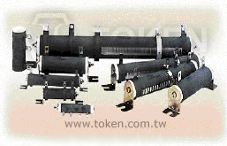

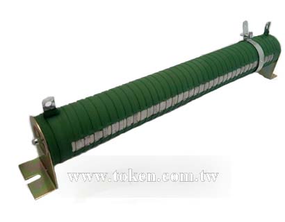
These high energy wire wounds are equipped with an adjustable lug, making them ideal for adjusting circuits, obtaining unique resistance values and setting equipment to meet various line voltages.
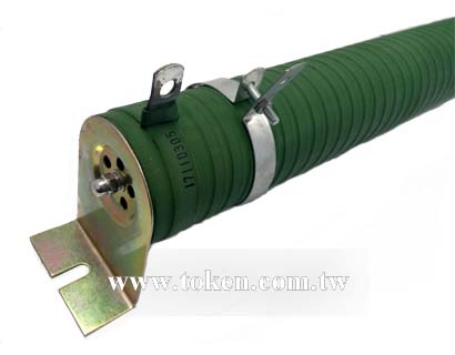
DRS resistors feature a hollow core to permit secure fastening with thru bolts with washers or spring-type clips. They also offer the durability of lead free vitreous enamel, or silicone coating and all-welded construction.
The Power (DRS) Adjustable Resistor is RoHS compliant and lead free. For non-standard technical requirements and custom special applications, please contact us.
Downloads complete PDF version Smooth Wound Power Adjustable Resistors (DRS).
To Calculate Max. Amperes: Voltage = (Watts x Ohms) 1/2
- Resistance Tolerance: J(±5%), K(±10%).
- Flame resistant and rugged lead coating.
- Terminals suitable for soldering or bolt connection.
- Adjustable lug supplied. High wattage applications.
- Adjustable, fixed, or tapped styles are available.
- Special terminals available for non-standard applications.
- Single and double quick connect terminals can be specified.
- Standard lug terminals available with or without terminal hardware.
- Non-inductive Ayrton Perry windings can be specified.
- Special temperature coefficients, tolerances
- Based on 25°C free air rating. The stated wattage rating applies only when the entire resistance is in the circuit.
- Setting the lug at an intermediate point reduces the wattage rating by approximately the same proportion.
- Example: If the lug is set at half resistance, the wattage is reduced by approximately one-half.
- Wattage is proportional to this adjusted resistance value.
- Adjustability is 10% to 90% of full resistance value.
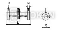
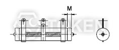
Dimensions (DRS-A 20W ~ 1300W)
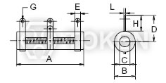
(DRSA) N - No Mount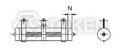
(DRSA) Z - Vertical Mount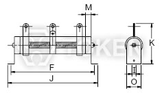
(DRSA) G - Horizontal Mount |
||||||||||||||||
| Wattage Rating |
Dimensions (Unit: mm) | Max. Pickable Resistance Value (Ω) | ||||||||||||||
| A | B | C | D | E | F | G | H | I | J | K | L | M | N | O | ||
| 20W | 60 | 17 | 8 | 22 | 5 | 78 | 2 | 12 | 4 | 90 | 36 | 1.0 | - | 6 | 16 | 1~150Ω |
| 30W | 80 | 17 | 8 | 22 | 5 | 100 | 2 | 12 | 4 | 112 | 36 | 1.0 | - | 6 | 16 | 1~250Ω |
| 40W | 110 | 17 | 8 | 22 | 5 | 128 | 2 | 12 | 4 | 140 | 36 | 1.0 | - | 6 | 16 | 1~400Ω |
| 50W | 110 | 25 | 16 | 30 | 8 | 150 | 5 | 18 | 6 | 166 | 58 | 1.2 | 6 | - | 27 | 1.5~500Ω |
| 60W | 90 | 28 | 18 | 32 | 8 | 130 | 5 | 19 | 6 | 146 | 60 | 1.2 | 6 | - | 27 | 1.5~550Ω |
| 80W | 110 | 28 | 18 | 32 | 8 | 150 | 5 | 19 | 6 | 166 | 60 | 1.2 | 6 | - | 27 | 2~650Ω |
| 100W | 140 | 28 | 18 | 32 | 8 | 180 | 5 | 19 | 6 | 196 | 60 | 1.2 | 6 | - | 27 | 2~750Ω |
| 120W | 160 | 28 | 18 | 32 | 8 | 200 | 5 | 19 | 6 | 216 | 60 | 1.2 | 6 | - | 27 | 3~850Ω |
| 150W | 195 | 28 | 18 | 32 | 8 | 235 | 5 | 19 | 6 | 251 | 60 | 1.2 | 6 | - | 27 | 3~1.2KΩ |
| 160W | 185 | 35 | 24 | 36 | 10 | 225 | 5 | 19 | 8 | 245 | 76 | 1.6 | 6 | - | 34 | 5~1.3KΩ |
| 200W | 210 | 35 | 24 | 36 | 10 | 250 | 5 | 19 | 8 | 274 | 76 | 1.6 | 6 | - | 34 | 6~1.5KΩ |
| 250W | 210 | 40 | 25 | 38 | 12 | 250 | 5 | 20 | 8 | 274 | 78 | 1.6 | 6 | - | 34 | 6~2KΩ |
| 300W | 260 | 40 | 25 | 38 | 12 | 300 | 5 | 20 | 8 | 320 | 78 | 1.6 | 6 | - | 34 | 7~2.5KΩ |
| 400W | 330 | 40 | 25 | 38 | 12 | 370 | 5 | 20 | 8 | 395 | 78 | 1.6 | 6 | - | 34 | 8~3.5KΩ |
| 500W | 330 | 50 | 35 | 50 | 12 | 380 | 6 | 25 | 9 | 400 | 100 | 1.6 | 8 | - | 40 | 8~4.5KΩ |
| 600W | 400 | 50 | 35 | 50 | 12 | 450 | 6 | 25 | 9 | 470 | 100 | 1.6 | 8 | - | 40 | 8~5.5KΩ |
| 700W | 460 | 50 | 35 | 50 | 12 | 510 | 6 | 25 | 9 | 530 | 100 | 1.6 | 8 | - | 40 | 12~7KΩ |
| 800W | 460 | 60 | 40 | 55 | 15 | 515 | 6 | 30 | 10 | 535 | 110 | 1.6 | 10 | - | 50 | 12~8KΩ |
| 1000W | 540 | 60 | 40 | 55 | 15 | 595 | 6 | 30 | 10 | 615 | 110 | 1.6 | 10 | - | 50 | 15~9KΩ |
| 1300W | 650 | 65 | 42 | 62 | 15 | 702 | 6 | 30 | 10 | 722 | 115 | 1.6 | 10 | - | 50 | 15~11KΩ |
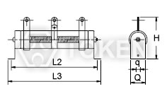
Dimensions (DRSB 15W ~ 20000W)
(DRSB) |
|||||||||||
| Wattage Rating |
Dimensions (Unit: mm) | Max. Pickable Resistance Value (Ω) | |||||||||
| R | L1 | L2 | L3 | H | N | d | M | q | Q | ||
| 15W | 15 | 45 | 65 | 85 | 40 | 6 | 3.5 | 3.5 | 4.5 | 15 | 1~1KΩ |
| 20W | 15 | 50 | 70 | 90 | 40 | 6 | 3.5 | 3.5 | 4.5 | 15 | 1~1KΩ |
| 25W | 20 | 50 | 80 | 100 | 50 | 6 | 3.5 | 5 | 5 | 20 | 2~1KΩ |
| 30W | 20 | 70 | 100 | 120 | 50 | 6 | 3.5 | 5 | 5 | 20 | 2~1KΩ |
| 40W | 20 | 87 | 115 | 137 | 50 | 6 | 3.5 | 5 | 5 | 20 | 2~1KΩ |
| 50W | 28 | 90 | 115 | 143 | 68 | 9 | 4.5 | 5.5 | 6 | 27 | 5~1KΩ |
| 80W | 28 | 90 | 115 | 143 | 68 | 9 | 4.5 | 5.5 | 6 | 27 | 5~2KΩ |
| 100W | 28 | 170 | 195 | 223 | 68 | 9 | 4.5 | 5.5 | 6 | 27 | 10~3KΩ |
| 150W | 28 | 215 | 240 | 268 | 68 | 9 | 4.5 | 5.5 | 6 | 27 | 10~3KΩ |
| 200W | 28 | 267 | 292 | 320 | 68 | 9 | 4.5 | 5.5 | 6 | 27 | 10~5KΩ |
| 250W | 28 | 267 | 292 | 320 | 68 | 9 | 4.5 | 5.5 | 6 | 27 | 10~5KΩ |
| 300W | 40 | 267 | 300 | 343 | 90 | 10 | 4.5 | 6 | 6 | 39 | 20~5KΩ |
| 400W | 40 | 330 | 365 | 406 | 90 | 10 | 4.5 | 6 | 6 | 39 | 20~5KΩ |
| 500W | 50 | 330 | 365 | 415 | 98 | 10 | 6 | 8.5 | 8 | 49 | 20~5KΩ |
| 600W | 50 | 330 | 365 | 415 | 98 | 10 | 6 | 8.5 | 8 | 49 | 20~5KΩ |
| 700W | 50 | 400 | 435 | 485 | 95 | 10 | 6 | 8.5 | 8 | 49 | 20~5KΩ |
| 800W | 70 | 300 | 320 | 362 | 138 | 15 | 8 | - | 8 | 69 | 40~500Ω |
| 1000W | 70 | 300 | 320 | 362 | 138 | 15 | 8 | - | 8 | 69 | 40~500Ω |
| 1500W | 70 | 415 | 435 | 477 | 138 | 15 | 8 | - | 8 | 69 | 40~500Ω |
| 2000W | 70 | 510 | 530 | 572 | 138 | 15 | 8 | - | 8 | 69 | 40~500Ω |
| 2500W | 70 | 600 | 620 | 662 | 138 | 15 | 8 | - | 8 | 69 | 40~500Ω |
| 3000W | 70 | 600 | 620 | 662 | 138 | 15 | 8 | - | 8 | 69 | 40~500Ω |
| 4000W | 100 | 430 | 450 | 521 | 155 | 15 | 8 | - | 8 | 99 | 40~500Ω |
| 5000W | 100 | 500 | 620 | 691 | 155 | 15 | 8 | - | 8 | 99 | 40~500Ω |
| 6000W | 100 | 600 | 720 | 791 | 155 | 15 | 8 | - | 8 | 99 | 40~500Ω |
| 10000W | 150 | 600 | 625 | 720 | 350 | 30 | 8 | - | 10 | 150 | 40~500Ω |
| 12000W | 150 | 660 | 685 | 780 | 350 | 30 | 8 | - | 10 | 150 | 40~500Ω |
| 15000W | 150 | 660 | 685 | 780 | 350 | 30 | 8 | - | 10 | 150 | 40~500Ω |
| 20000W | 150 | 1000 | 1030 | 1120 | 350 | 30 | 8 | - | 10 | 150 | 40~500Ω |
Specification (DRS)
| Test Item | Test Methods | Characterstics |
| Load life | JIS-C-5202 7-10 90 minutes ON - 30 minutes OFF500 hours |
Free of appearance or structural irregularity Surface coating crack ΔR/R≤ ±(1%+0.05Ω) |
| Load rating | JIS-C-5202 5-4 | ΔR/R≤±(0.5%+0.1Ω) Surface temperature up 350°C MAX |
| Humidity | JIS-C-5202 7-5 40°C 90%RH 240 hours |
Free of appearance or structural irregularity Surface coating crack ΔR/R≤ ±(3%+0.1Ω) |
| Vibration | JIS-C-5202 6-3 1.5m/m 10 ~ 50 ~ 10 Hz/min X-Y-Z 2 hours each |
Free of appearance or structural irregularity Surface coating crack ΔR/R≤ ±(1%+0.05Ω) |
| Thermal shock | JIS-C-5202 7-3 Room temp 30 minutes ON-55°C 15 minutes OFF |
Free of structural irregularity ΔR/R≤ ±(2%+0.1Ω) |
| Terminal strength | JIS-C-5202 6-1 8kg 30 seconds | Free of appearance or structural irregularity |
| Flame retardation | JIS-C-5202 7-13-3-2 100% - 600% rated wattage load |
US UL-94 flame retardation test V-0 grade noncombustible |
| Resistance tolerance | JIS-C-5202 5-1 | Resistance |
| Short-term overload | JIS-C-5202 5-5 1000% rated wattage 5 seconds |
Free of appearance or structural irregularity ΔR/R≤ ±(2%+0.1Ω) |
| Insulation resistance | JIS-C-5202 5-6 500VDC | 100MΩ min |
| Temperature coefficient | JIS-C-5202 5-2 | ±200PPM/°C MAX |
| Dielectric withstanding voltage | JIS-C-5202 5-7 1000VDC 1 minute Between terminal and anchor stand |
Free of appearance or structural irregularity ΔR/R≤ ±(0.1%+0.05Ω) |
| REMARKS: | 1. Resistance and resistance tolerance were tested in-house with micro resistance meter. 2. Coating refers to UL-certified data provided by supplier. |
|
Application Notes of Adjustable Wirewound (DQS)
Determination of End Resistance Value of FVR, DQS, DSRA, DSRB, BSR, BSQ:
- Resistance Range means you can choose one maximum resistance value (Max. Pickable Resistance / End resistance value)
at one of FVR, DQS, DSRA, DSRB, BSR, BSQ VR (Variable Resistor) type. - After End Resistance Value confirmed, the minimum resistance (start resistance value) will be determined
by depending on resistance of wire and wirewound type.
Power Rating of Variable Resistor:
The part Nunber formation of FVR, DQS, DSRA, DSRB, BSR, BSQ:
Product type - Rated Wattage - Max. Pickable Resistance (Ω) - Resistance Tolerance
Product type means one of FVR, DQS, DSRA, DSRB, BSR, BSQ.
Rated Wattage means power rating at End Resistance Value.
Resistance Value
(Ω) means maximum resistance value (End Resistance Value).
Resistance Tolerance means precision range of End Resistance Value.
1. Power Rating of VR (Variable Resistor) is determined by the maximum resistance value (End Resistance Value).
2. Resistance and Power Rating should be decreased while you are adjusting the screw.
Power Rating:
- Based on 25°C free air rating. The stated wattage rating applies only when the entire resistance is in the circuit.
- Setting the lug at an intermediate point reduces the wattage rating by approximately the same proportion.
- Example: If the lug is set at half resistance, the wattage is reduced by approximately one-half.
- Adjustability is 10% to 90% of full resistance value.
- Wattage is proportional to this adjusted resistance value.
If you need current constant type or special specifications, please feel free to cntact us.
Order Codes (DRS)
| DRSA | 600W | 250R | J | G | ||||||||||||||||||||||||||||||||||||||
 |
|
|
|
|
||||||||||||||||||||||||||||||||||||||
|
|
|
|
|
||||||||||||||||||||||||||||||||||||||