Custom Design Power Resistor Load Bank/Chamber (RNW)
Custom Design Power Chamber (RNW) Introduction
Token's (RNW) Power Modules Simplify Your Power Resistor Chamber Design
<
>
Token Electronics produces various kinds of power load bank/chamber which can be used for any resistor, chamber AC or DC power application. Units are most commonly used for motor acceleration and braking, load banks, harmonic filtering and neutral grounding applications.
The series is lead-free and RoHS compliant. Detailed specifications, both mechanical and electrical, please contact our sales representative for more information.
Download complete datasheet Power Load Bank Resistor Chamber (RNW) PDF (307KB).
Assembly:
- All units are coiled consist of stainless steel edge wound non-inductive elements wound around core which is mounted on a stainless steel rod.
- Glazed insulators are attached to each end of the coils and fastened to a heavy gage, corrosion resistant frame.
- Resistor elements are joined by stainless connectors to form a positive electrical path.
Safety Enclosure:
- Token resistor assemblies are available with grounded safety enclosures to protect personnel and wildlife from harm.
- Screened and louvered enclosures are available in a variety of finishes including painted, powder coated, mill galvanized, hot-dipped galvanized, aluminum and stainless steel.
Safety Enclosure:
- A number of additional options are available including entrance bushings, current transformers, elevating stands and disconnect switches.
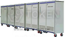
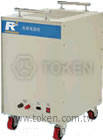
Load Bank Appearance (RNW)
(RNW) Load Bank Appearance - 1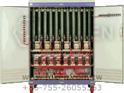
(RNW) Load Bank Appearance - 2 |
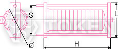
Electric Parameter and External Dimensions (RNW-T)
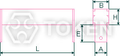
Load Bank Unit (RNW-T) Dimensions |
||||||
| Type | Wattage ( W ) | Dimensions (Unit: mm) | ||||
| L | H | B | A | E | ||
| T5 | 5 | 35 | 9 | 9 | 6 | 15 |
| T10 | 10 | 48 | 10 | 10 | 6 | 15 |
| T20 | 20 | 64 | 14 | 14 | 8 | 20 |
| T30 | 30 | 75 | 19 | 19 | 8 | 20 |
| T50 | 50 | 88 | 20 | 20 | 10 | 20 |
| T100 | 100 | 135 | 25 | 25 | 10 | 25 |
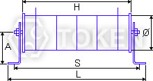
Electric Parameter and External Dimensions (RNW-B)
Load Bank Unit (RNW-B) Dimensions |
||||||||
| Series | Resistance Range ( Ω ) | Capacity ( KJ ) | Dimensions (Unit: mm) | Mounting Hole | ||||
| Ø | H | L | Quantity [N] | Diameter [Ø] | Center Spacing [S] | |||
| B11 | 0.5-30 | 400 | 110 | 190 | 185 | 2 | 10.5 | 158 |
| B12 | 0.5-60 | 800 | 110 | 290 | 185 | 2 | 10.5 | 158 |
| B13 | 0.5-90 | 1200 | 110 | 390 | 185 | 2 | 10.5 | 158 |
| B21 | 0.5-30 | 300 | 110 | 214 | 254 | 2 | 10.5 | 238 |
| B22 | 0.5-60 | 600 | 110 | 370 | 410 | 2 | 10.5 | 294 |
| B23 | 0.5-90 | 900 | 110 | 526 | 566 | 2 | 10.5 | 550 |
Electric Parameter and External Dimensions (RNW-H)
Load Bank Unit (RNW-H) Dimensions |
|||||||||
| Series | Rated Wattage ( W ) |
Resistance Range ( Ω ) |
Dimensions (Unit: mm) | Mounting Hole | Center Height [A] |
||||
| Ø | H | L | Quantity [N] | Diameter [Ø] | Center Spacing [S] | ||||
| H | 200 | 1-30 | 100 | 134 | 174 | 2 | 8.5 | 158 | 90 |
| 400 | 2-60 | 100 | 194 | 234 | 2 | 8.5 | 218 | ||
| 500 | 3-90 | 100 | 254 | 294 | 2 | 8.5 | 278 | ||
| 750 | 4-120 | 100 | 314 | 354 | 2 | 8.5 | 338 | ||
| 1000 | 5-150 | 100 | 374 | 414 | 2 | 8.5 | 398 | ||
- All dimensions might be changed or modified, please refer to last updating specification.