Flat Power Wirewound Mica Resistors (ASM)
Flat Mica Resistor (ASM) Introduction
High Performance Therm And Electrical Insulation of Token Flat Mica Resistors Improve Power Capacity.
Token has introduced a new line of high-power, high-current mica flat resistors (ASM) in standard planar bank sizes. Offering designers a lower cost option to the standard space-saving design, Token (ASM) compact mica resistors feature flat wirewound technology for improvements in low electric current loss, excellent thermal stability, and power capacity, while maintaining the same package size.
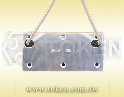
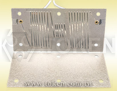
The (ASM) resistor is compact in structure, and the resistance wire is wound on the mica substrate, and both sides are insulated with mica sheets. To ensure symmetrical expansion of the resistor and maximum stability to high load pulses, the device is packaged in a thin metal alloy case made of aluminum and zinc. For the resistance winding, we use a high quality strip wires composed of CuNi, NiCr, or CrAl alloy. This ensures that even the resistor element reaches its maximum pulse load.
Due to its low profile, the (ASM) mica power resistor can be easily mounted on the back side of a Voltage to Frequency Converter (VFC). In particular, the (ASM) is fitting extremely well into the given space as an internal braking resistor and a series resistor for current limiting when charging the intermediate circuit capacitor of the frequency converter. Further application as load banks, dynamic braking, and motor control, or protective resistor. The nominal load can be improved by forced air cooling or by mounting the resistors on a heat sink.
The (ASM) flat mica resistor features with power handling capability of 100W to 400W and wide resistance range 1Ω to 10KΩ with Temperature Coefficients TCR ±260ppm/°C. The devices offer operating temperature form -55°C to +275°C with precision tolerance of ±5% and ±10% and conform to the RoHS directives and Lead-free.
To assist with your specifying power load and braking applications, please contact Token Electronics. For each load case, a thermal simulation can be calculated to determine the suitability of a given application. Customed design are also available on request.
Downloads Complete Specification in PDF Power Wirewound Flat Mica Resistors (ASM).
- Heat sink must be installed as required when it’s used.
- Excellent mechanical strength, high dielectric strength.
- Product is flat, thin and with small size and, Cost-Effective.
- Excellent high temperature load performance, low electric current loss.
- Perfect insulation, low moisture absorption, excellent Thermal stability.
- Load Test, Variable Frequency Power Source.
- Functional Power Supply, Electric Power Distribution.
- Driving and Braking Part of the Industrial Control System.
Construction & Dimensions (Unit: mm)
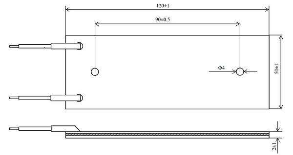
ASM-5002-100W Mica Plate Braking Resistor Dimensions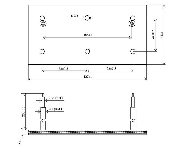
ASM-6405-200W Mica Power Resistor Dimensions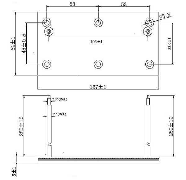
ASM-6405-300W Mica wirewound Resistor Dimensions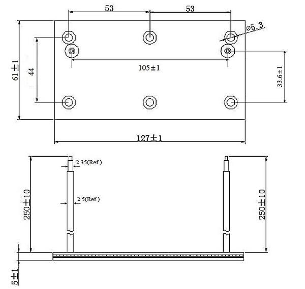
ASM-6105-400W Power Mica Resistor Dimensions |
Electrical Specification
| Type | Power Rating (W) | Resistance Range (Ω) | Tolerance (%) | TCR(ppm/°C) | Operating Voltage Max | Overload Voltage Max | Insulation voltage | Operating Temperature |
| ASM-5002 | 100W | 1~10K | J(±5%), K(±10%) | ±260 | √PR | √5PR | 1500VAC | -55 ~ +275°C |
| ASM-6405 | 200W | 1~10K | J(±5%), K(±10%) | |||||
| ASM-6405 | 300W | 1~10K | J(±5%), K(±10%) | |||||
| ASM-6105 | 400W | 1~10K | J(±5%), K(±10%) |
Electrical Characteristics
| No. | Test Item | Test Method | Characteristics |
| 1 | Operating Voltage Max | - | √PR |
| 2 | Overload Voltage Max | - | √5PR |
| 3 | Insulation voltage | - | 1500VAC |
| 4 | TCR | After measuring the resistance of the test resistor at room temperature, place it in a thermostatic chamber at -55°C and 125°C successively, and then measure the resistance after 30 to 50 minutes respectively. | ±260ppm/°C |
| 5 | Terminal strength | The resistor body should be firmly mounted, apply a predetermined direct pull force of 8 kg in the direction of the lead wire, and hold one end at a time for 10±1s. After the test, the resistor shall have no visible damage, and the change in resistance shall not be greater than ± (1.0%R+0.05Ω). | ΔR≤±(1.0%R+0.05Ω) |
| 6 | High temperature resistance | Place the resistor in a thermostat; raise it to 275±5°C, hold for 2 hours, then cool to room temperature. The appearance of the resistor should be free of mechanical damage. | ΔR≤±(1.0%R+0.05Ω) |
| 7 | Withstand voltage | The resistor is normally mounted on a metal plate. The metal plate should be larger than the resistor body. 1500 AC was applied for 1 minute and voltage was applied between the terminals connected together and the metal mounting plate. The resistor should be free from damage, arcing, flashing, and insulation breakdown. | ΔR≤±(1.0%R+0.05Ω) |
| 8 | Insulation resistance | DC 500V, Insulation resistance between terminal and cas e≥100MΩ. | Dry Condition:R≥100MΩ;After humidity test:R≥100MΩ |
| 9 | Thermal shock | The resistor is fixedly mounted on a stipulated aluminum chassis. The resistors should be properly ventilated. Apply the rated voltage of the power supply until it reaches thermal stability. Then cut off the voltage. Within 8 to 12 seconds, place the resistor in a thermostatic chamber at -55±5°C for 15 to 30 minutes. After 2 hours of removal, measure the resistance again. The change in resistance before and after the test shall not be greater than: ± (1.0% R + 0.05 Ω). The resistor should be free of mechanical damage. | ΔR≤±(1.0%R+0.05Ω) |
| 10 | Short-time overload | The resistor is fixedly mounted on a stipulated aluminum chassis. The resistors should be properly ventilated. Apply 5 times the power rating of the power supply for 5 seconds. After the resistor is stabilized at room temperature, the resistance is measured. The change in resistance before and after the test shall not be greater than: ± (1.0% R + 0.05 Ω). The resistor shall be free of arcing, charring and charring. | ΔR≤±(1.0%R+0.05Ω) |
| 11 | Moisture resistance | MIL-STD-202 The terminal shall be free of cracks, cracks, loosening or corrosion. Insulation resistance should not be less than 100MΩ. | ΔR≤±(1.0%R+0.05Ω) |
| 12 | Long-time life | The resistor is fixedly mounted on a stipulated aluminum chassis. The resistors should be properly ventilated. The rated voltage of the applied power supply is 1000h, 1.5h pass and 0.5h cut. and the resistor shall be free of mechanical damage. Insulation resistance should not be less than 100MΩ. | ΔR≤±(1.0%R+0.05Ω) |
| 13 | Impact Test | The test resistor shall be subjected to the 213 method of MIL-STD-202. The sign of the test condition is I, acceleration: 100 g, pulse duration: 6 ms, sawtooth wave. After the test, the resistor shall have no visible damage, The resistor shall be able to meet the specified dielectric pressure requirements. | ΔR≤±(1.0%R+0.05Ω) |
| 14 | High frequency vibration | MIL-STD-202, Method 204. The vibration frequency of the vibration table gradually increases from 10HZ to 2000HZ, and then gradually decreases from 2000HZ to 10HZ. The frequency change is completed in 20 minutes, and the amplitude should be 1.5mm. According to the above method, the X, Y, and Z axes were scanned 12 times in each of the three directions. The total duration was about 12 hours. The resistor shall be free of mechanical damage and shall be able to meet the specified dielectric pressure requirements. | ΔR≤±(1.0%R+0.05Ω) |
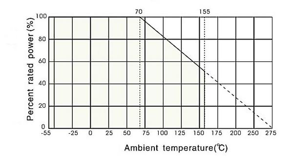
Derating Curve
|
|||||||||||||
Mica Power Resistor - Order Codes (ASM)
| ASM-6105 | 400W | 20R | J | ||||||||||||||||||||||||
 |
|
|
|
||||||||||||||||||||||||
|
|
|
|
||||||||||||||||||||||||