TO247 Power Pulse-loading Resistors (RMG100)
(RMG100) Pulse-loading TO247 Resistors - Introduction
TO-247 Power Resistors handle high-speed pulses
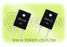
Providing design engineers with a high-power resistive device in a stable transistor style package, Token Electronics RMG100 Series TO-247 power resistors are available in 100W.
The resistors are specified for applications that require accuracy and stability. The RMG100 Series resistors are designed with an alumina ceramic layer that separates the resistance element and mounting tab.
This construction provides very low thermal resistance while ensuring high insulation resistance between the terminals and the metal back plate. As a result, the resistors feature a very low inductance, making them ideal for high frequency and high-speed pulse applications.
Additional applications for the RMG100 Series TO-247 resistors include automation test equipment, high frequency snubber and pulse handling circuits, motor control and drive circuits, switch mode power supplies, load resistors, automotive electronics, industrial power equipment, UPS systems and industrial computers.
RMG100 Series 100W resistors feature a resistance range of 0.1Ω to 10KΩ and operating temperature range is -65°C to +175°C.
Token will also produce devices outside these specifications to meet customer requirements. The RMG100 Series power resistors are RoHS-compliant with Pb-free Terminations. Contact us with your specific needs.
Download PDF Specification TO247 Power Pulse-loading Resistors (RMG100).
- Molded Case for Protection and Easy to Mount.
- Non-Inductive Design, Electrically Isolated Case.
- 100 Watts at 25°C Case Temperature Heat Sink Mounted.
- TO-247 Style Power Package. Single M3 Screw Mounting to Heat Sink.
- Terminal Resistance in RF Power Amplifiers.
- Low Energy Pulse Loading, Gate Resistors in Power Supplies.
- UPS, Snubbers, Voltage Regulation, Load and Dumping Resistors in CRT Monitors.
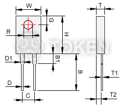
(RMG100) Pulse-loading TO247 Resistor - Dimensions (Unit: mm)
Pulse Loading TO-247 Power Resistor |
||||||||||||||||||||||||||||||
| RMG100 Dimensions (Unit: mm) | |||||
| W | H | T | T1 | T2 | B |
| 15.49~16.01 | 20.44~20.96 | 4.69~5.21 | 0.55~1.07 | 2.15~2.67 | 13.21~15.75 |
| B1 | C | D | D1 | G | R |
| 2.03~3.55 | 9.90~10.42 | 1.42~1.62 | 3.45~3.81 | 5.07~5.59 | 3.53~3.73 |
(RMG100) Electrical Characteristics Specifications
| Resistance Range | Resistance Tolerance | TCR(PPM/°C) |
| 0.1Ω~1Ω | ±5% ±10% |
- |
| >1Ω~3Ω | ±1% | ±300 |
| >3Ω~10Ω | ±1% ±5% ±10% |
±100 ±200 |
| >10Ω~10KΩ | ±1% ±5% ±10% |
±50 ±100 ±200 |
- Operating Voltage: 700V Max. Dielectric Strength: 1800V AC. Insulation Resistance: 10GΩ min.
- Working Temperature Range: -65°C to +175°C. Resistance Value: < 1Ω is available.
(RMG100) Environmental Characteristics
| Test Item | Specification | Test Method |
| Temperature Coefficient of Resistance | As spec. | Referenced to 25°C, ΔR taken at +105°C |
| Short Time Overload | ΔR±0.5% | 1.5 times rated power with applied voltage not to exceed 1.5 times maximum continuous operating voltage for 5 seconds. |
| Dielectric strength | ΔR±0.15% | MIL-STD-202F Method 301(1800V AC, 60s) |
| Load Life | ΔR±1.0% | MIL-PRF-39009D, 4.8.13 Rated power, 2,000 hours. |
| Moisture resistance | ΔR±0.5% | -10°C~+65°C, RH>90%, cycle 240 hours. |
| Thermal Shock | ΔR±0.5% | MIL-STD-202, Method 107G. -65°C~150°C,100 cycle |
| Terminal Strength | ΔR±0.2% | MIL-STD-202F, Method 211, Cond. A (Pull Test) 2.4N |
| Vibration, High Frequency | ΔR±0.42% | MIL-STD-202F, Method 204, Cond.D |
| Solderability | 90% min coverage | MIL-STD-202F Method 208H 245°C±5°C, 3±0.5 (sec) |
- Lead Material: Tinned Copper. Thermal Grease Should be Applied Properly.
- When in Free Air at 25°C, the RMG100 is Rated for 3.5W.
- The Case Temperature is to be used for the Definition of the Applied Power Limit.
- The Case Temperature Measurement Must be Made with a Thermocouple Contacting the Center of the Component Mounted on the Designed Heat Sink.
(RMG100) Power Derating Curve
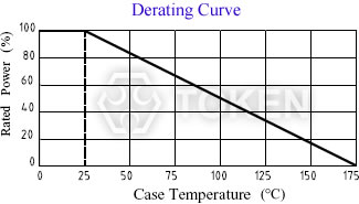
(RMG100) Power Derating Curve |
(RMG100) Order Codes
| RMG | 100 | J | P | D | 10R | ||||||||||||||||||||||||||||||||||||||||||||||
 |
|
|
|
|
|
||||||||||||||||||||||||||||||||||||||||||||||
|
|
|
|
|
|
||||||||||||||||||||||||||||||||||||||||||||||