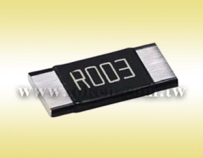
High Power Low Value Current Sensing Chip Resistors (LRE) Metal Strip
High Power Current Sensing Chips (LRE) - Introduction
Token (LRE) Metal Strip Chips offer exclusive technology features and benefits for current-sensing.
For current sensing applications, metal strip (metal alloy) resistors provide a more robust technology than thick film and thin film devices. Both thin film and thick film resistor technologies need a ceramic substrate for support.
Power Metal Strip technologies are quite different from thick film or thin film technologies since it is an exciting-metal welded construction that's thick enough to become self-supporting (there's no substrate). It's because the big current transporting mass of the bulk alloy, which supplies greater surge capacity. The ability of power handling capacity offers greater power rating and/or extended really low resistance ranges.
In fast electrical transients such as mechanical switch closures or battery plug-in, the pulse capability of the resistor is limited to the amount of heat energy that causes a temperature rise in the resistor element. The more massive resistor element of the power metal strip device will have less temperature rise for the same pulse energy, which translates to superior pulse withstanding capability.
Unlike other manufacturers of metal element current sense resistors, Token (LRE) metal strip chip resistors design for applications that require high power handling (Up to 5W) and low resistance values from 0.25mΩ to 1Ω at ±50 ppm/°C; and come with a range of advantages including a wide temperature range and a varied choice of wide range package sizes 0805/1206/2010/2512/2725/2728/2817/4527 with high current capability.
Token (LRE) series enable a wide range of design options and flexibility allows designers to specify the resistance value and tolerance that their circuits require, instead of designing their circuits to the resistance values available. At the same time, Token electronics also offers AEC-Q200 Automotive Grade (LREA) specifications by extending (LRE) series for vehicle applications such as electronic controls (anti-lock brakes, audio electronics, engine and transmission controls, climate controls, etc.).
Token electronics delivers the right chip for your low range, current-sense applications. For more detailed product information and data sheets or to discuss your specific requirements please contact Token electronics. Downloads Complete Specification PDF High Power Current Sensing Metal Strip Chip Resistors (LRE).
- High power rating up to 5 Watts. Low TCR down to ±50 ppm/°C.
- Resistance values 0.25mΩ to 1Ω. Customized resistance available.
- Wide range package sizes 0805/1206/2010/2512/2725/2728/2817/4527.
- Power Management for NB, MB, Monitor.
- SWPS DC-DC Converter, Charger, Adaptor, Power Supplies.
- Hard Disk Drives: Solid-state hard drives (SSD), Solid-state hybrid drives (SSHD).
- The resistive layer is covered with a protective coat, and two external end terminations are added.
- Internal metal electrodes are added at each end and connected by a resistive paste that is applied to the top surface of the metal alloy.
- Wrap-around terminations have an electroplated nickel barrier and pure Tin (lead free) or matte-tin finish, ensuring excellent "leach" resistance properties and solderability.
Metal Strip Chip (LRE) Construction & Dimensions
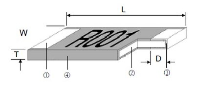
Construction & Dimensions (Unit: mm) |
||||||||||||||
| 1 | Solder Plating (Sn) |
| 2 | Alloy Plate |
| 3 | Barrier Layer (Cu, Ni) |
| 4 | Overcoat |
| Type | Power Rating at 70℃ (W) | Resistance Range (mΩ) | Dimensions (Unit: mm) | |||
| L | W | T | D | |||
| LRE0805 | 0.75 | 3.0 ~100.0 | 2.100±0.254 | 1.500±0.254 | 0.320±0.254 | 0.400±0.254 |
| 1.0 | 3.0 ~10.0 | |||||
| LRE1206 | 0.5 | 51.0 ~ 100.0 | 3.200±0.254 | 1.650±0.254 | 0.300±0.254 | 0.508±0.254 |
| 0.75 | 21.0~50.0 | 0.390±0.254 | ||||
| 1.0 | 1.0~2.0 | 0.670±0.254 | ||||
| 3.0~100.0 | 0.490±0.254 | |||||
| 1.5 | 1.0~2.0 | 0.670±0.254 | ||||
| 3.0~100.0 | 0.490±0.254 | |||||
| LRE2010 | 0.75 | 71.0~100.0 | 5.100±0.254 | 2.400±0.254 | 0.310±0.254 | 0.840±0.254 |
| 1 | 31.0~70.0 | 0.460±0.254 | ||||
| 1.5 | 1.0~2.0 | 0.670±0.254 | ||||
| 2.5~30.0 | 0.460±0.254 | |||||
| 31.0~100.0 | 0.590±0.254 | |||||
| LRE2512 | 1 | 0.5~1.0 | 6.350±0.254 | 3.050±0.254 | 0.670±0.254 | 2.200±0.254 |
| 1.5 | 0.560±0.254 | 2.000±0.254 | ||||
| 2.0 | 1.400±0.254 | |||||
| 2.5~100.0 | 1.100±0.254 | |||||
| 101.0~680.0 | 0.490±0.254 | 0.850±0.254 | ||||
| 2 | 0.5~1.0 | 0.670±0.254 | 2.200±0.254 | |||
| 1.5 | 0.560±0.254 | 2.000±0.254 | ||||
| 2.0 | 1.400±0.254 | |||||
| 2.5~100.0 | 1.100±0.254 | |||||
| 101.0~450.0 | 0.610±0.254 | 0.850±0.254 | ||||
| 3 | 0.5~1.0 | 6.350±0.254 | 3.050±0.254 | 0.670±0.254 | 2.200±0.254 | |
| 1.5 | 2.000±0.254 | |||||
| 2.0 | 1.400±0.254 | |||||
| 2.5~50.0 | 1.100±0.254 | |||||
| 51.0~100.0 | 0.740±0.254 | |||||
| LRE2725 | 4 | 0.25 | 6.800±0.254 | 6.350±0.254 | 0.820±0.254 | 2.300±0.254 |
| 0.5 | 0.690±0.254 | |||||
| 1 | 0.690±0.254 | 1.800±0.254 | ||||
| 1.5~3.0 | 0.610±0.254 | |||||
| LRE2728 | 4 | 4.0~50.0 | 6.600±0.254 | 6.700±0.254 | 0.720±0.254 | 1.200±0.254 |
| 51.0~450.0 | 0.840±0.254 | |||||
| 451.0~600.0 | 0.770±0.254 | |||||
| LRE2817 | 3 | 1.0 | 7.300±0.254 | 4.400±0.254 | 0.690±0.254 | 1.800±0.254 |
| 2.0~30.0 | 0.610±0.254 | 1.500±0.254 | ||||
| 31.0~100.0 | 0.720±0.254 | |||||
| 101.0~130.0 | 0.770±0.254 | |||||
| 131.0~200.0 | 0.690±0.254 | |||||
| LRE4527 | 3 | 501.0~680.0 | 11.300±0.500 | 6.600±0.500 | 0.770±0.254 | 2.000±0.254 |
| 681.0m~1.0R | 0.690±0.254 | |||||
| 5 | 1.0 | 0.790±0.254 | 3.000±0.254 | |||
| 1.5 | 0.840±0.254 | 2.000±0.254 | ||||
| 2.0~500.0 | 0.840±0.254 | |||||
Current Sensing Metal Strip Chip (LRE) Electrical Specifications
| Type | Max. Rating Power (W) | Max. Rating Current (A)* | Max. Overload Current (A) | Resistance Range (mΩ)* | TCR (ppm/°C) | OperatingTemperature (°C) | |
| D (±0.5%) | F (±1%); G (±2%); J (±5%) |
||||||
| LRE0805 | 0.75 | 15.81 | 31.62 | 10.0~100.0 | 3.0~100.0 | ±50 | -55~+170°C |
| 1 | 18.26 | 36.51 | 10.0 | 3.0~10.0 | |||
| LRE1206 | 0.50 | 3.13 | 6.26 | 51.0~100.0 | 51.0~100.0 | ||
| 0.75 | 5.98 | 11.95 | 21.0~50.0 | 21.0~50.0 | |||
| 1 | 31.62 | 63.25 | 7.0~100.0 | 1.0~100.0 | |||
| 1.5 | 38.73 | 67.08 | 7.0~100.0 | 1.0~100.0 | |||
| LRE2010 | 0.75 | 3.25 | 7.27 | 71.0~100.0 | 71.0~100.0 | ||
| 1 | 5.68 | 12.70 | 31.0~70.0 | 31.0~70.0 | |||
| 1.5 | 38.73 | 77.46 | 7.0~100.0 | 1.0~100.0 | |||
| LRE2512 | 1 | 44.72 | 100.00 | 7.0~680.0 | 0.5~680.0 | ||
| 2 | 63.25 | 141.42 | 7.0~450.0 | 0.5~450.0 | |||
| 3 | 77.46 | 134.16 | 7.0~100.0 | 0.5~100.0 | |||
| LRE2725 | 4 | 126.49 | 252.98 | -- | 0.25~3.0 | ||
| LRE2728 | 4 | 31.62 | 54.77 | 7.0~600.0 | 4.0~600.0 | ||
| LRE2817 | 3 | 54.77 | 109.54 | 7.0~200.0 | 1.0~200.0 | ||
| LRE4527 | 3 | 2.45 | 4.24 | 501m~1.0R | 501m~1.0R | ||
| 5 | 70.71 | 122.47 | 7.0~500.0 | 1.0~500.0 | |||
- Note: Rating Current I= √ ( P / R ) or Max. Rating Current whichever is lower.
- Special tolerance and range of resistance are under requested.
Metal Strip Chip (LRE) Recommend Land Pattern
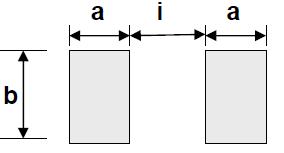
Metal Strip Chip (LRE) Recommend Land Pattern |
|||||
| Type | Maximum Power Rating (Watts) | Resistance Range (mΩ) | Dimensions (mm) | ||
| a | b | i | |||
| LRE0805 | 0.75 | 3.0 ~ 100.0 | 1.80 | 2.18 | 0.66 |
| 1.0 | 3.0 ~ 10.0 | 1.80 | 2.18 | 0.66 | |
| LRE1206 | 0.5 & 0.75 &1.0 & 1.5 | 1.0 ~ 100.0 | 1.60 | 2.18 | 0.66 |
| LRE2010 | 0.75 & 1.0 &1.5 | 1.0 ~ 3.0 | 2.89 | 2.92 | 1.22 |
| 3.1 ~ 100.0 | 2.29 | 2.92 | 2.41 | ||
| LRE2512 | 1.0 & 2.0 & 3.0 | 0.5 ~1.5 | 3.05 | 3.68 | 1.27 |
| 2.0 ~ 3.5 | 2.11 | 3.68 | 3.18 | ||
| 3.6 ~ 680.0 | 1.90 | 3.68 | 3.50 | ||
| LRE2725 | 4.0 | 0.25 ~ 0.5 | 3.18 | 6.86 | 1.32 |
| 4.0 | 1.0 ~ 3.0 | 2.34 | 6.86 | 3.00 | |
| LRE2728 | 4.0 | 4.0 ~600.0 | 2.75 | 7.82 | 3.51 |
| LRE2817 | 3.0 | 1.0 ~ 3.0 | 2.75 | 7.82 | 3.51 |
| 3.0 | 3.5 ~200.0 | 2.45 | 7.82 | 3.11 | |
| LRE4527 | 3.0 & 5.0 | 1.0 ~ 3.0 | 4.50 | 8.74 | 4.50 |
| 3.5 ~100.0 | 3.4 | 8.74 | 6.43 | ||
| 101.0m ~ 1R | 2.93 | 8.74 | 7.63 | ||
Reel Specifications (LRE) Unit: mm
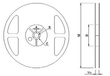
Reel Specifications Dimensions |
||||||||
| Reel Type / Tape | W | M | A | B | C | D | ||
| 7” reel for 8 mm embossed (LRE0805 & 1206 series only) | 12.00± 0.5 | 178 ± 1.0 | 2.0 ± 0.5 | 13.2 ± 0.5 | 17.7 ± 0.5 | 60.0 ± 0.5 | ||
| 7” reel for 12 mm embossed | 16.2 ± 0.5 | 178 ± 1.0 | 2.5 ± 0.5 | 13.5 ± 0.5 | 17.7 ± 0.5 | 60.0 ± 0.5 | ||
| 7” reel for 24 mm embossed (LRE4527 series only) | 24.4 +2/-0 | 178 ± 1.0 | 2.0 ± 0.5 | 13.2 ± 0.5 | 17.7 ± 0.5 | 60.0 ± 0.5 | ||
Emboss Plastic Tape Specifications (LRE) Unit: mm
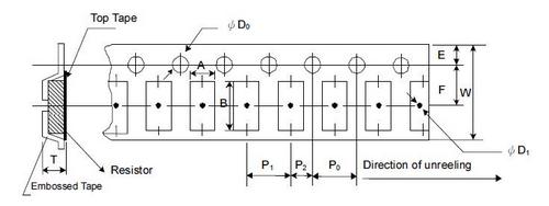
Low Ohm Metal Strip (LRE) Emboss Plastic Tape Specifications |
||||||||||||
| Type | A±0.1 | B±0.1 | W±0.3 | E±0.1 | F±0.1 | P0±0.1 | P1±0.3 | P2±0.1 | ΦD0±0.05 | ΦD1±0.1 | T±0.1 | |
| LRE0805 | 1.70 | 2.45 | 8.0 | 1.75 | 3.5 | 4.0 | 4.0 | 2.0 | 1.55 | 1.00 | 0.50 | |
| LRE1206 | 2.03 | 3.55 | 8.0 | 1.75 | 3.5 | 4.0 | 4.0 | 2.0 | 1.55 | 1.00 | 0.70 | |
| LRE2010 | 2.85 | 5.55 | 12.0 | 1.75 | 5.5 | 4.0 | 4.0 | 2.0 | 1.55 | 1.55 | 0.82 | |
| LRE2512 | 3.50 | 6.75 | 12.0 | 1.75 | 5.5 | 4.0 | 4.0 | 2.0 | 1.55 | 1.55 | 0.90 | |
| LRE2725 | 6.81 | 7.16 | 12.0 | 1.75 | 5.5 | 4.0 | 8.0 | 2.0 | 1.55 | 1.55 | 1.05 | |
| LRE2728 | 7.10 | 7.05 | 12.0 | 1.75 | 5.5 | 4.0 | 8.0 | 2.0 | 1.55 | 1.55 | 0.95 | |
| LRE2817 | 4.60 | 7.50 | 12.0 | 1.75 | 5.5 | 4.0 | 8.0 | 2.0 | 1.55 | 1.55 | 1.20 | |
| LRE4527 | 7.38 | 12.0 | 24.0 | 1.75 | 11.5 | 4.0 | 12.0 | 2.0 | 1.55 | 1.55 | 1.05 | |
- The cumulative tolerance of 10 sprockets hole pitch is ± 0.2mm.
- Carrier camber shall be not more than 1mm per 100mm through a length of 250mm.
- A & B measured 0.3mm from the bottom of the packet
- T measured at a point on the inside bottom of the packet to the top surface of the carrier.
- Pocket position relative to sprocket hole is measured as the true position of the pocket and not the pocket hole.
Packaging Quantity (LRE)
| Type | Tape Width | Diameter | Pieces/Reel |
| LRE0805 | 8 mm/embossed plastic | 178 mm/7” | 5,000 |
| LRE1206 | 8mm/embossed plastic | 178mm/7” | 5,000 |
| LRE2010 | 12 mm/embossed plastic | 178 mm/7” | 4,000 |
| LRE2512 | 12 mm/embossed plastic | 178 mm/7” | 4,000 |
| LRE2725 | 12 mm/embossed plastic | 178 mm/7” | 2,000 |
| LRE2728 | 12 mm/embossed plastic | 178 mm/7” | 2,000 |
| LRE2817 | 12 mm/embossed plastic | 178 mm/7” | 1,000 |
| LRE4527 | 24 mm/embossed plastic | 178 mm/7” | 1,000 |
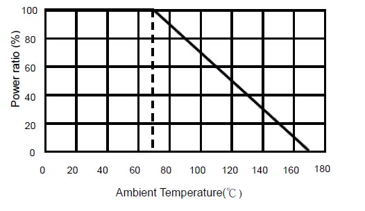
Derating Curve (LRE)
 |
Soldering Condition (Reflow Soldering only) (LRE)
 |
Environmental Characteristics (LRE)
| Item | Requirement | Test Method | ||
| Temperature Coefficient of Resistance(T.C.R.) | As Spec. | JIS C 5201-1 4.8 +25/+125°C | ||
| Short Time Overload | LRE4527: ΔR/R0≤±2.0% The others: ΔR/R0≤±0.5% | JIS C 5201-1 4.13 Rating power duration: 5secs. | ||
| Type | Power | Multiple | ||
| LRE0805 | 0.75W, 1.0W | 4 times | ||
| LRE1206 | 0.5W, 0.75W,1.0W | 4 times | ||
| LRE1206 | 1.5W | 3 times | ||
| LRE2010 | 0.75W, 1.0W | 5 times | ||
| LRE2010 | 1.5W | 4 times | ||
| LRE2512 | 1.0W, 2.0W,3.0W | 5 times | ||
| LRE2725 | 4.0W | 4 times | ||
| LRE2728 | 4.0W | 3 times | ||
| LRE2817 | 3.0W | 4 times | ||
| LRE4527 | 3.0W, 5.0W | 3 times | ||
| Solderability | 95% Min. coverage | JIS-C5201-1 4.17 245±5°C for 3 seconds | ||
| Resistance to Soldering Heat | ΔR/R0≤± 0.5% | JIS-C5201-1 4.18 260±5°C for 10 seconds | ||
| Temperature Cycling | ΔR/R0≤± 0.5% | JIS-C5201-1 4.19 -55°C ~ 150°C, 100 cycles | ||
| BiasHumidity | ΔR/R0≤± 0.5% | JIS-C5201-1 4.24 +85°C/85%RH for 1,000Hrs. with 1.5Hrs “ON”, 0.5Hr “OFF”. | ||
| High Temperature Exposure (Storage) | LRE4527: ΔR/R0≤±2.0% The others: ΔR/R0≤±1.0% | JIS-C5201-1 4.23.2 +170°C for 1000 Hrs. | ||
| Load Life | LRE4527: ΔR/R0≤±2.0% The others: ΔR/R0≤±1.0% | JIS-C5201-1 4.25 70±2°C, RCWV for 1000 Hrs. with 1.5 Hrs. “ON” and 0.5 Hr. “OFF” | ||
Order Codes (LRE)
| LRE | 2728 | F | TR | D | 4 | R010 | |||||||||||||||||||||||||||||||||||||||||||||||||||||||||||||||||||||||||||||||||||||
 |
|
|
|
|
|
|
|
||||||||||||||||||||||||||||||||||||||||||||||||||||||||||||||||||||||||||||||||||||
|
|
|
|
|
|
|
|
||||||||||||||||||||||||||||||||||||||||||||||||||||||||||||||||||||||||||||||||||||
- Note: There is no marking on 0805 series.