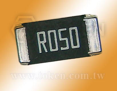
Low Ohmic Metal Strip Chip Resistors (LRP)
Low Value Chip Resistor (LRP) Introduction
Things go better with Token (LRP) high power metal strip chip, a very low value resistor.
(LRP) Low ohm metal strip resistors from Token Electronics offer a wide range of high-power current sensing applications including power management of NB, MB and monitor, automotive, shunts and power amplifiers, DC-DC converter and charger, test & measurement instruments, linear power supplies and switching.
(LRP) Design for applications that require high power handling (Up to 3W) and low resistance values from 7mΩ to 100mΩ and come with a range of advantages including a wide temperature range and a varied choice of wide range package sizes 2512 with high current capability.
Token (LRP) is aiming for very high power-to-footprint size ratio, excellent frequency response and very low inductance in a solid metal nickel-chrome or manganese-copper allow resistive element with Low TCR ±50PPM/°C. Also, ideal for all types of voltage division, current sensing and pulse applications.
(LRP) series as current detection and current divider chips can be customized according to customers'needs. For special resistance value and latest product information, contact us with your specific needs.
Downloads Complete Specification PDF Metal Strip chip high Power Low Ohmic Resistors (LRP).
- Very low inductance without Laser trimmed.
- Customized Resistance Available. High power rating from 1W to 3W.
- Low TCR ±50PPM/°C, ±75PPM/°C. Low resistance value 7mΩ to 100mΩ.
- SWPS: DC-DC converter, Charger, Adaptor.
- For NB power management. For MB power management. For Monitor power management.
Chip 2512 (LRP) Dimensions & Construction
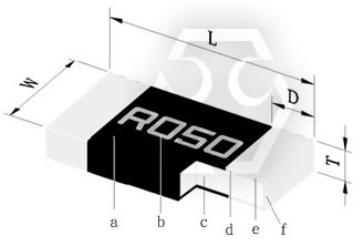
Power Metal Strip Chip 2512 (LRP) Dimensions & Construction
|
| Type | Size (Inch) | L(mm) | W(mm) | T(mm) | D(mm) |
| LRP12 | 2512 | 6.40±0.25 | 3.20±0.25 | 0.70±0.20 | 0.90±0.30 |
- TOKEN is capable of manufacturing the optional spec based on customer's requirement.
Electrical Specifications Chip 2512 (LRP)
| Type | Power Rating at 70°C | Operating Temp. Range | Resistance Tolerance (±%) | Resistance (mΩ) | TCR (±PPM/°C) |
| LRP12 (2512) | 1W, 2W, 3W | -55°C ~ +170°C | ±0.5%, ±1%, ±5% | 15, 18, 20, 22, 25, 30, 33, 35, 39, 40, 47, 50, 60, 68, 70, 75, 80, 82, 90, 91, 100 | ±50 |
| 7, 8, 9, 10, 12, 15, 18, 20, 22, 25, 30, 33, 35, 39, 40, 47, 50, 60, 68, 70, 75, 80, 82, 90, 91, 100 | ±75 |
- Operating Current I =√ ( P / R ) , Operating Voltage V =√ ( P * R )
- Token is capable of manufacturing the optional spec based on customer’s requirement.
Derating Curve (LRP)
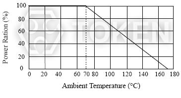 (LRP) Power Derating Curve |
Recommend Land Pattern (LRP)
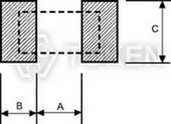
Recommend Land Pattern |
|||
| Type | A (mm) | B (mm) | C (mm) |
| LRP12 | 4.00 | 2.00 | 3.50 |
- *FR4 copper board, 100μm of copper pad thickness.
Packing Quantity & Reel Specifications (LRP)
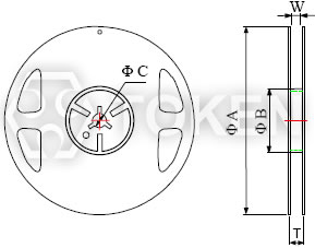
Reel Specifications Dimensions |
||||||||
| Type | Packaging Quantity | Tape Width | Reel Diameter | ΦA (mm) | ΦB (mm) | ΦC (mm) | W (mm) | T (mm) |
| LRP12 | Embossed 4,000 pcs | 12 mm | 7 inch | 178.0±1.5 | 60.0±1.0 | 13.0±0.5 | 13.0±1.0 | 15.5±0.5 |
Emboss Plastic Tape Specifications (LRP)
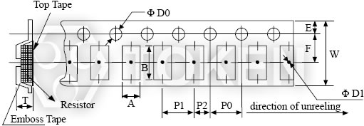 Low Ohm Metal Strip (LRP) Emboss Plastic Tape Specifications |
||||||||||||
| Type | A (mm) | B (mm) | W (mm) | E (mm) | F (mm) | P0 (mm) | P1 (mm) | P2 (mm) | ΦD0 (mm) | ΦD1 (mm) | T | |
| LRP12 | 3.50±0.10 | 6.70±0.10 | 12.0±0.30 | 1.75±0.10 | 5.5±0.05 | 4.0±0.10 | 4.0±0.10 | 2.0±0.05 | 1.50±0.10 | 1.50±0.25 | 1.2±0.15 | |
- The cumulative tolerance of 10 sprocket hole pitch is ±0.2mm.
- Carrier camber shall be not more than 1mm per 100mm through a length of 250mm.
- A & B measured 0.3mm from the bottom of the packet.
- t measured at a point on the inside bottom of the packet to the top surface of the carrier.
- Pocket position relative to sprocket hole is measured as the true position of the pocket and not the pocket hole.
Soldering Condition (Reflow Soldering only) (LRP)
 (LRP) Reflow Soldering |
- Time of IR reflow soldering at maximum temperature point 260°C:10s.
- Time of soldering iron at maximum temperature point 410°C:5s
Environmental Characteristics (LRP)
| Item | Requirement | Test Method |
| Thermal Shock |
±1%
|
IEC-60115-1 4.19 JIS-C-5201-1 4.19 -55°C ~ 155°C, 5 cycles |
| Short Time Overload |
±1%
|
IEC60115-1 4.13 JIS-C-5201-1 4.13 5*rated power for 5 seconds |
| Low Temperature Storage |
±1%
|
IEC-60115-1 4.23.4 JIS-C-5201-1 4.23.4 at-55°C for 1000 hrs |
| Biased Humidity |
±1%
|
MIL-STD-202 Method 103 1000 hrs 85°C/85% RH 10% of operating power |
| Bending Stength |
±1%
|
IEC-60115-1 4.33 JIS-C-5201-1 4.33 Bending width 2mm once for 5 seconds |
| Endurance |
±1%
|
IEC60115-1 4.25 JIS-C-5201-1 4.25.1 70±2°C, RCWV for 1000 hrs with 1.5 hrs “ON” and 0.5 hrs “OFF” |
| Dry Heat |
±1%
|
IEC60115-1 4.23.2 JIS-C-5201-1 4.23.2 at +170°C for 1000 hrs |
| Resistance to Soldering Heat |
±0.5%
|
IEC-60115-1 4.18 JIS-C-5201-1 4.18 260±5°C, for 10 seconds |
| Insulation Resistance |
>100MΩ
|
IEC60115-1 4.6 JIS-C-5201-1 4.13 100V DC for 1 minute |
| Solderability |
95% min coverage
|
IEC-60115-1 4.17 JIS-C-5201-1 4.17 245±5°C for 3 seconds |
| Temperature Coefficient of Resistance (T.C.R.) |
As Spec.
|
IEC60115-1 4.8 JIS-C-5201-1 4.8 -55°C ~+125°C. (25°C is the reference temperature) |
- Rated continuous Working Voltage (RCWV) = √ Power Rating × Resistance Value (Ω)or Max. Operating voltage whichever is lower.
- Storage Temperature: 25±3°C; Humidity < 80%RH;
Order Codes (LRP)
| LRP | 12 | F | TR | D | S | R050 | ||||||||||||||||||||||||||||||||||||||||||
 |
|
|
|
|
|
|
|
|||||||||||||||||||||||||||||||||||||||||
|
|
|
|
|
|
|
|
|||||||||||||||||||||||||||||||||||||||||