Thin Film Current Sensing Precision Chip Resistors (TCS)
Current Sensing Resistor (TCS) Introduction
Token's Thin Film Current Sensing Resistor (TCS) makes sense of current.
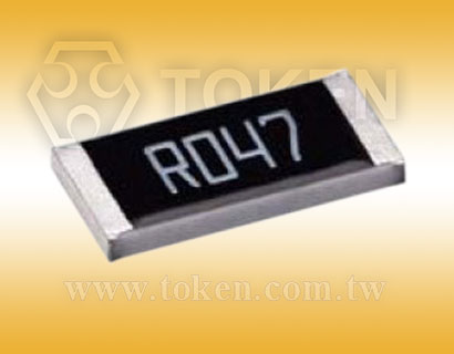
The trend towards smaller handheld and portable electronics equipment has also increased the need for ultra small current sensing resistor. Devices from the Token Electronics' TCS series use a thin film construction that enables them to achieve precision resistance tolerances, low noise and long-term stability.
The Token TCS Series precision resistors are nichrome thin film chip resistors with a temperature coefficient of resistance of just ±50PPM/°C and tolerances of ±0.5%.
They offer excellent stability at high frequencies and are suitable for operating high voltages with more options in the smaller form sizes of 0402, 0603, 0402, 0805, 1206, 2010, and 2512.
The full range of values is from 50mΩ to 1Ω. This low ohmic devices are particularly suited to car engine management units to act as current shunt resistors.
The TCS current sense series is fully RoHS compliant and is supplied in tape and reel packaging ready for use with automated assembly processes. Contact us with your specific needs.
Downloads Complete Specification PDF Surface Mount Current Sensing Precision Resistor.
- Thin Film Process. Resistance Value 50mΩ to 1Ω.
- High Purity Alumina Substrate for Power Dissipation.
- Extremely Low TCR from ±200 PPM/°C to ±50PPM/°C.
- RoHS Requirments with Pb-free Terminations. Tolerance ±1% to ±0.5%.
- Automotive Engine Control, Power Management Applications,
- Over Current Protection in Audio Application, DC-DC Converter,
- Voltage Regulation Module (VRM), Switching Power Supply, Adaptor,
- Disk Driver, Charger,Portable Devices (PDA, Cell phone), Battery Pack,
Construction & Dimensions (Unit: mm) (TCS)
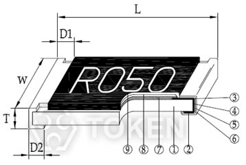
Thin Film Chip Construction
|
| Type | L (Unit: mm) | W (Unit: mm) | T (Unit: mm) | D1 (Unit: mm) | D2 (Unit: mm) | Weight(g)/1000pcs |
| TCS02 (0402) | 1.00±0.05 | 0.50±0.05 | 0.32±0.10 | 0.25±0.10 | 0.20±0.10 | 0.56 |
| TCS03 (0603) | 1.60±0.10 | 0.80±0.10 | 0.45±0.10 | 0.30±0.20 | 0.30±0.20 | 3.1 |
| TCS05 (0805) | 2.00±0.15 | 1.25±0.15 | 0.55±0.10 | 0.30±0.20 | 0.40±0.25 | 5.6 |
| TCS06 (1206) | 3.05±0.15 | 1.55±0.15 | 0.55±0.10 | 0.50±0.30 | 0.40±0.25 | 12.3 |
| TCS10 (2010) | 5.00±0.20 | 2.45±0.15 | 0.60±0.15 | 0.60±0.30 | 0.50±0.25 | 26.7 |
| TCS12 (2512) | 6.35±0.20 | 3.15±0.15 | 0.60±0.10 | 0.60±0.30 | 0.55±0.25 | 49.6 |
Standard Electrical Specifications Thin Film (TCS)
| Type | Power Rating at 70°C | Resistance Tolerance | Resistance Range | TCR | Operating Temp. Range |
| TCS02 (0402) | 1/16W | ±0.5%, ±1.0% | 500mΩ~1000mΩ | ±100PPM/°C ±50PPM/°C |
-55 ~ +155°C |
| TCS03 (0603) | 1/10W | ±0.5%, ±1.0% | 200mΩ~300mΩ 301mΩ~1000mΩ |
±100PPM/°C ±50PPM/°C |
|
| TCS05 (0805) | 1/8W | ||||
| TCS06 (1206) | 1/4W | ±1.0% | 50mΩ~100mΩ | ±200PPM/°C ±100PPM/°C ±50PPM/°C |
|
| ±0.5%,±1.0% | 101mΩ~300mΩ 301mΩ~1000mΩ |
||||
| TCS10 (2010) | 3/4W | ±0.5%,±1.0% | 50mΩ~100mΩ 101mΩ~300mΩ 301mΩ~1000mΩ |
±200PPM/°C ±100PPM/°C ±50PPM/°C |
|
| TCS12 (2512) | 1W |
High Power Rating Electrical Specifications Thin Film (TCS)
| Type | Power Rating at 70°C | Resistance Tolerance | Resistance Range | TCR | Operating Temp. Range |
| TCS12 (2512) | 3W | ±0.5%, ±1.0% | 100mΩ~1000mΩ | ±100PPM/°C | -55 ~ +155°C |
- Token has the ability to manufacture following options based on customer's requirement.
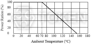
Power Derating Curve (TCS)
|
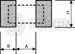
Recommend Land Pattern (TCS)
|
||||
| Type | A (mm) | B (mm) | C (mm) | |
| TCS02 | 0.50 | 0.50 | 0.60±0.2 | |
| TCS03 | 0.80 | 1.00 | 0.90±0.2 | |
| TCS05 | 1.00 | 1.00 | 1.35±0.2 | |
| TCS06 | 2.00 | 1.15 | 1.70±0.2 | |
| TCS10 | 3.60 | 1.40 | 2.50±0.2 | |
| TCS12 | 4.90 | 1.60 | 3.10±0.2 | |
Reflow Soldering (TCS)
|

Environmental Characteristics (TCS)
| Item | Specification | Test Method |
| Temperature Coefficient of Resistance | As Spec | MIL-STD-202F Method 304 +25/-55/+25/+125/+25°C |
| Short Time Overload | ±1% | JIS-C-5202-5.5 RCWV*2.5 or Max. overload voltage whichever is lower for 5 seconds |
| Dielectric Withstand Voltage | by Type | MIL-STD-202F Method 301 Apply Max Overload Voltage for l minute |
| Insulation Resistance | >1000MΩ | MIL-STD-202F Method 302 Apply 100VDC for 1 minute |
| Thermal Shock | ±0.5% | MIL-STD-202F Method 107G -55°C~150°C, 100cycles |
| Load Life (Endurance) | ±1% | MIL-STD-202F Method 108A 70±2°C, RCWV for 1000 hrs with 1.5 hrs “ON” and 0.5 hrs “OFF” |
| Humidity (Damp Heat with Load) | ±0.5% | MIL-STD-202F Method 103B 40°C, 90~95%RH, RCWV 1.5 hours ON, 0.5 hours OFF, total 1000 hours |
| Low Temperature Operation | ±0.5% | JIS-C-5202-7.1 1hour, -65°C followed by 45minutes of RCWV |
| Bending Strength | As Spec | JIS-C-5202-6.1.4 Bending Amplitude 3mm for 10seconds |
| Solderability | 95%min coverage | MIL-STD-202F Method 208H 245°C±5°C, 3 seconds |
| Resistance to Soldering Heat | ±0.5% | MIL-STD-202F Method 210E 260±5°C, 10±1 seconds |
|
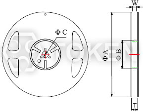
Packaging Quantity & Reel Specifications (TCS)
|
||||||||
| Type | ΦA | ΦB | ΦC | W | T | Paper Tape (EA) | Emboss Plastic Tape (EA) | |
| TCS02 | 178.0±1.0 | 60.0±1.0 | 13.5±0.7 | 9.5±1.0 | 11.5±1.0 | 10,000 | - | |
| TCS03 | 178.0±1.0 | 60.0±1.0 | 13.5±0.7 | 9.5±1.0 | 11.5±1.0 | 5,000 | - | |
| TCS05 | 178.0±1.0 | 60.0±1.0 | 13.5±0.7 | 9.5±1.0 | 11.5±1.0 | 5,000 | - | |
| TCS06 | 178.0±1.0 | 60.0±1.0 | 13.5±0.7 | 9.5±1.0 | 11.5±1.0 | 5,000 | - | |
| TCS10 | 178.0±1.0 | 60.0±1.0 | 13.5±0.7 | 13.5±1.0 | 15.5±1.0 | - | 4,000 | |
| TCS12 | 178.0±1.0 | 60.0±1.0 | 13.5±0.7 | 13.5±1.0 | 15.5±1.0 | - | 4,000 | |
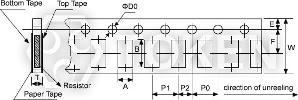
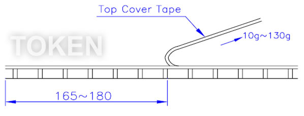
Paper Tape Specifications (TCS)
|
|||||||||||
|
|||||||||||
| Type | A | B | W | E | F | P0 | P1 | P2 | ΦD0 | T | |
| TCS02 | 0.70±0.05 | 1.16±0.05 | 8.00±0.10 | 1.75±0.05 | 3.50±0.05 | 4.00±0.10 | 2.00±0.10 | 2.00±0.05 | 1.55±0.05 | 0.40±0.03 | |
| TCS03 | 1.10±0.05 | 1.90±0.05 | 8.00±0.10 | 1.75±0.05 | 3.50±0.05 | 4.00±0.10 | 4.00±0.10 | 2.00±0.05 | 1.55±0.05 | 0.60±0.03 | |
| TCS05 | 1.60±0.05 | 2.37±0.05 | 8.00±0.10 | 1.75±0.05 | 3.50±0.05 | 4.00±0.10 | 4.00±0.10 | 2.00±0.05 | 1.55±0.05 | 0.75±0.05 | |
| TCS06 | 2.00±0.05 | 3.55±0.05 | 8.00±0.10 | 1.75±0.05 | 3.50±0.05 | 4.00±0.10 | 4.00±0.10 | 2.00±0.05 | 1.55±0.05 | 0.75±0.05 | |
|
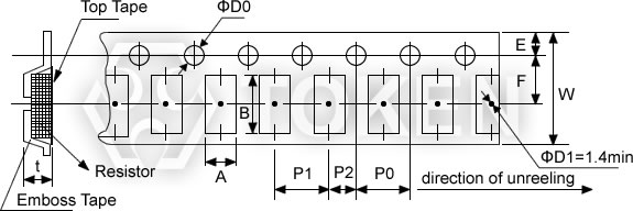
Emboss Plastic Tape Specifications (TCS)
|
|||||||||||
| Type | A | B | W | E | F | P0 | P1 | P2 | ΦD0 | T | |
| TCS10 | 2.85±0.10 | 5.45±0.10 | 12.0±0.10 | 1.75±0.10 | 5.5±0.05 | 4.00±0.05 | 4.00±0.10 | 2.00±0.05 | 1.50+0.10 | 1.00±0.20 | |
| TCS12 | 3.40±0.10 | 6.65±0.10 | 12.0±0.10 | 1.75±0.10 | 5.5±0.05 | 4.00±0.05 | 4.00±0.10 | 2.00±0.05 | 1.50+0.10 | 1.00±0.20 | |
Order Codes (TCS)
| TCS | 02 | D | TR | E | 1R00 | N | ||||||||||||||||||||||||||||||||||||||||||||||||||||||||
 |
|
|
|
|
|
|
|
|||||||||||||||||||||||||||||||||||||||||||||||||||||||
|
|
|
|
|
|
|
|
|||||||||||||||||||||||||||||||||||||||||||||||||||||||
3 Digit Marking (0603) (TCS)
| Resistance | 1Ω | 0.1Ω | 0.15Ω | 0.01Ω | 0.101Ω | 0.035Ω |
| Codes | 1R0 | R10 | R15 | R01 | 101 | 035 |
4 Digit Marking (0805~2512) (TCS)
| Resistance | 1Ω | 0.1Ω | 0.05Ω | 0.015Ω | 0.01Ω | 0.39Ω |
| Codes | 1R00 | R100 | R050 | R015 | R010 | R390 |